
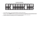
Specifications

5
There may be electrical wiring between the
roof and the ceiling. Disconnect 120 VAC
power cord and the positive (+) 12 VDC ter-
minal at the supply battery. Failure to obey
this instruction may create a shock hazard
causing death or severe personal injury.
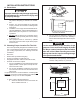
C. Roof Preparation
1. Opening Requirements - Before preparing the ceil-
ing opening, the type of system options must be
decided upon. Read all of the following instructions
before beginning the installation.
2. Mark a 14-1/4" x 14-1/4" (±1/8") square on the roof
and carefully cut the opening. The 14-1/4" x 14-1/4"
(±1/8") opening is part of the return air system of
the unit and must be nished in accordance with
ANSI A119.2.
3. Using the roof opening as a guide, cut the matching
hole in the ceiling.
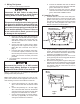
4. The opening created must be framed to provide
adequate support and prevent air from being drawn
from the roof cavity. Framing stock 3/4" or more in
thickness must be used. Remember to provide an
entrance hole for power supplies, three conductor
cable, and furnace wiring (if applicable).
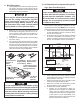
Do Not Cut Roof
Structure Or
Rafters
Good-Rafters
Supported By
Cross Beams
Good Location-
Between Roof
Rafters
Frame Opening So It
Won't Collapse When
Bolting Down Unit
Leave Access For Power
Supply Wiring
15" Min. At
Front Of
Opening
3/4" Min.
It is the responsibility of the installer of this
system to ensure structural integrity of the RV
roof. Never create a low spot on the roof where
water will collect. Water standing around the
unit may leak into the interior causing damage
to the product and the RV.
FIG. 3
D. Air Distribution Duct System Sizing & De-
sign (See Chart On Page 6)
The Installer of this system must design the air distri-
bution system for their particular application. Several
requirements for this system MUST be met for the unit
to operate properly. These requirements are as follows:
1. The duct material must meet or exceed any agency
or RVIA Standard that may be in existence at the
time the RV is produced.
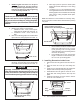
2. All discharge air ducts must be properly insulated
to prevent condensation from forming on their
surfaces or adjacent surfaces during operation of
the unit. This insulation must be R-7 minimum.
It is the responsibility of the installer to insure
the duct work will not collapse or bend dur-
ing and after the installation. Dometic, LLC
will not be liable for roof structural or ceiling
damage due to improperly insulated, sealed
or collapsed duct work.
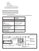
FIG. 4
3. Ducts and their joints must be sealed to prevent
condensation from forming on adjacent surfaces
during operation of the unit.
4. Return air openings must have 40 square inches
minimum free area including the lter.
5. Return air to the unit must be ltered to prevent
dirt accumulation on unit cooling surface.
6. Air Distribution System Installation
a. Dometic, LLC recommends the basic con-
guration shown on page 6, for installing this
system. We have found by testing, that this
conguration works best in most applications
of this system. It is the responsibility of the
installer of this system to review each RV oor
plan and determine the following:
Frame
14-1/4" (±1/8")
Opening
AC Power
Supply Wire
Duct
Frame
Duct
Roof
Insulation
Duct
Ceiling
Duct
14-1/4" (±1/8")
Opening
Insulation
SIDE VIEW
(TOWARD BACK OF RV)
TOP VIEW
(BACK OF RV)
Low Voltage Wires:
12 VDC
Furnace
Frame
3 Conductor
Communication
Cable