
Specifications
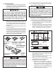

7
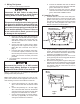
F. Choosing Thermostat Location
The proper location of the thermostat is very impor-
tant to ensure that it will provide a comfortable RV
temperature. Observe the following rules when se-
lecting a location:
1. Locate the thermostat 54" above the oor.
2. Install the thermostat on a partition, not on an out-
side wall.
3. NEVER expose the thermostat to direct heat from
lamps, sun or other heat producing items.
4. Avoid locations close to doors that lead outside,
windows or adjoining outside walls.
5. Avoid locations close to supply registers and the
air from them.
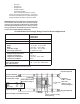
E. Wiring Requirements
1. Route a copper, with ground, 120 VAC supply
wire from the time delay fuse or circuit breaker
box to the roof opening. The proper size wire can
be determined from chart on page 3.
a. This supply wire must be located in the front
portion of the 14-1/4" x 14-1/4" (±1/8") open-
ing.
b. The power MUST be on an appropriately
sized separate time delay fuse or circuit
breaker. The proper size protection can be
determined from the chart on page 3.
c. Make sure that at least 15" of supply wire ex-
tends into the roof opening. This insures an
easy connection at the junction box.
d. Wiring must comply with the National Electri-
cal Code ANSI/NFPA-70 and CSA Standard
C22.1 (latest edition) and any State or Local
Codes or regulations.
e. Protect the wire where it passes into the
opening with approved method. See para-
graph "d" above.
2. Route a dedicated 12 VDC supply wire (18-22
AWG) from the RV's converter (ltered side) or
battery to the roof opening.
a. This supply wire must be located in the front
portion of the 14-1/4" x 14-1/4" (±1/8") open-
ing.
b. Make sure that at least 15" of supply wire ex-
tends into the roof opening.
3. Route a three conductor cable, 18 to 22 AWG,
from the Single Zone LCD (hereinafter referred
to as SZLCD) thermostat mounting position into
the 14-1/4" x 14-1/4" (±1/8") roof opening. Make
sure that at least 15" of the wire extends into the
roof opening and 6" extend from the wall at the
mounting position of the SZLCD thermostat. See
Section E.
4. If system includes a gas furnace, route two 18
gauge thermostat wires from the furnace to the
roof opening of the unit that will control it. If more
than one furnace is to be used, route the second
set of thermostat wires to the second unit. Make
sure that 15" of wire extends into the opening.
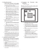
G. Thermostat and Thermostat Cable
Installation
1. SZLCD Thermostat
Note: Wire colors listed for the three conductor cable
match the wire colors in the harness at the SZLCD control
box. Available wire colors may vary.
a. Remove the cover from the SZLCD thermo-
stat. Depress tab on bottom of thermostat
and separate it from the base.
b. Insert the previously run three (3) conductor
cable through the hole in the base assembly.
c. Cut back the outer cable shield approximate-
ly 3 inches and strip 1/4" insulation from each
wire.
d. Mount the thermostat level on the wall using
the screws provided.
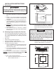
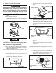
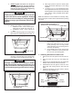
e. Make the following connections to the ther-
mostat. See FIG 6.
• Red/white wire to the 12V+ terminal
• Black wire to the 12V– terminal
• Orange wire to the "COMMS" terminal
f. Inspect all connections to make sure they are
tight and not touching any other terminals or
wires.
g. Push the wires back through the base into
the wall. Place cover on the thermostat and
push until an audible click is heard.
FIG. 6
12V-
COMMS
12V+