
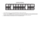
Specifications

8
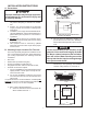
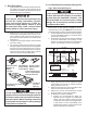
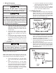
H. Placing The Unit On The Roof
1. Remove the unit from the carton and discard
carton.
2. Place the unit on the roof.
3. Lift and place the unit over the prepared open-
ing using the gasket on the unit as a guide. See
FIG. 7.
4. Place the return air cover kit inside the RV. This
box contains mounting hardware for the unit and
will be used inside the RV.
This completes the outside work. Minor adjustments can
be done from inside the RV if required.
Front
Personal injury hazard. This unit weighs ap-
proximately 100 pounds. To prevent back
injury, use a mechanical hoist to place unit
on roof. Failure to obey this warning could
cause severe personal injury.
Property damage hazard. Do not slide the
unit. Failure to obey this warning may dam-
age the neoprene gasket attached to the bot-
tom and create a leaky installation.
FIG. 7
Do Not Slide
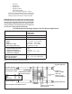
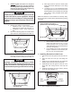
I. Installation Preparation
1. Check gasket alignment of the unit over the roof
opening and adjust if necessary. Unit may be moved
from below by slightly lifting. See FIG. 8.
Roof Gasket
FIG. 8
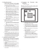
FIG. 11
Freeze Control
Sensor
Remove Hang
Tag
Route Up Through
Return Air Opening
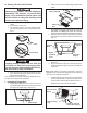
Divider Plate
Ceiling Template
Return Air
Cover
Return Air
Grill
FIG. 9
FIG. 10
Furnace
Wires
Gasket
Electrical
Cord
Control
Cables
AC Power
Supply
2. Remove return air cover and ceiling template from
carton.
3. All models listed in this manual will use a four (4)
bolt pattern for installing the return air cover kit.
These bolts are furnished in the SZLCD control kit.
4. Reach up into the return air opening and pull the
unit electrical cord down for later connection. See
FIG. 10.
5. If the control box being installed is plastic, remove
the cover.
6. Plug the electrical cord (6 pin connector) from the
upper unit into the mating connector in the SZLCD
control box.
Note: Plastic SZLCD control boxes will need to have the
supplied freeze control sensor plugged into the matching
connector in the SZLCD control box.
7. Insert the freeze control sensor into the evaporator
coil ns approximately 1" above the bottom of the
coil ns and on the left side as shown in FIG. 11.
Bend ns over sensor to secure in place.