
Specifications

9
J. Wiring The System
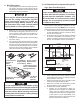
1. 120 VAC Power Supply Connection
a. Route the 120 VAC supply wire through the
strain relief in the SZLCD control box. Tighten
strain relief, making sure enough wire is in-
side SZLCD control box to connect with unit
120 VAC wires.
b. Connect the white to white; black to black;
and green or bare copper wire using appro-
priate size wire connectors. See chart on
page 3.
c. Push the wires into the SZLCD control box.
If control box is plastic, install the cover with
the four blunt point screws provided; if metal
install cover with the one blunt point screw
provided.
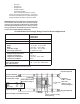
2. Low Voltage Wire Connections At The SZLCD
Control Box.
Note: If a solar panel is to be installed see instructions
packaged with solar panel option.
Note: Plastic SZLCD control boxes only. Plug the sup-
plied 4 wire harness and the supplied 2 blue wires into
their matching connectors in the SZLCD control box.
a. Connect the previously run +12 VDC supply
wire to the red wire from the SZLCD control
box.
b. Connect the previously run –12 VDC supply
wire to both the black wire from the SZLCD
control box and to wire of the three wire cable
that goes to the thermostat 12V– terminal.
c. Connect the previously run furnace thermo-
stat wires (if applicable) to the blue wires
coming from the SZLCD control box.
Disconnect 120 VAC. Failure to obey these
instructions could create a shock hazard
causing death or severe personal injury.
This product is equipped with a 3 wire (ground-
ed) system for protection against shock haz-
ard. Make sure that the unit is wired and that
you connect into a properly grounded 120 VAC
circuit and the polarity is correct. Failure to
do so could result in death, personal injury
or damage to the equipment.
Disconnect the positive (+) 12 VDC terminal
at the supply battery. Damage to equipment
could occur if the 12 VDC is not shut off.
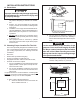
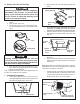
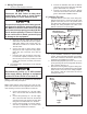
K. Installing The Unit
1. Install the SZLCD control box on the ceiling tem-
plate as shown in FIG. 12. Drive two (2) #6 x 3/8"
(plastic control box) or #10 x 3/8" (metal control
box) blunt point Phillips head screws (provided)
through the ceiling template into holes in the
SZLCD control box to hold into place.
2. If your installation includes the optional electric
heat kit, (457915 & 459516 models only) install it
at this time. Follow the instructions with the heat
package for its installation procedure.
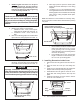
3. Hold the ceiling template up to the 14-1/4" x 14-1/4"
(±1/8") opening. Be sure the large plate faces the
rear of the RV. See FIG. 13.
4. Start each mounting bolt through the ceiling tem-
plate and up into the unit base pan by hand. Install
wood screw in each end of the ceiling template.
This insures a tight fit of the return air cover to
ceiling. See FIG. 13.
d. Connect the red/white wire from the SZLCD
control box to wire of the three wire cable that
goes to thermostat 12V+ terminal.
e. Connect the orange wire from the SZLCD
control box to wire of the three wire cable that
goes to thermostat COMMS terminal.
Finger
Tight
Front of Vehicle
Tighten To Com-
press Gasket To
1/2"
Roof
Gasket
Wood
Screws
FIG. 13
Metal Electronic
Control Box Shown
Blunt Self-Tapping
Screw
Front
Curb Side
FIG. 12