
User Manual


9
INSTALLATION INSTRUCTIONS
● The fl oor drain system (Fig. 9) requires an air
gap and siphon break that MUST be purchased
separately. The siphon break MUST be a mini-
mum of 23.6 inches (60 cm) from the bottom of
the appliance. Additional hoses may be needed.
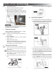
L. Fastening and Leveling the Appliance
If the template is not placed fl ush with the back
wall of the installation area, measure its location
to ensure proper alignment of the appliance.
2. Align the appliance with the template and se-
cure the brackets with screws on the exposed
bracket sides. Next, remove the template
and fi nish securing the brackets. Note: The
slot openings must be facing toward the front.
3. Ensure the fl oor’s surface is protected against
damage. Slide the appliance and align the rear
legs to the rear bracket slot openings. Ensure
that the legs are within ¼ inch from the back of
the slot.
4. Level the machine using the front legs.
a. When positioning the laundering machine,
ensure the front legs are in the shortest po-
sition that will allow room for the foot to fi t
inside the bracket. If not, adjust the legs to
their shortest position by hand and tighten
the nuts with a wrench.
b. After positioning the appliance, ensure that it
is stable by pressing on the four corners of
the appliance. If the appliance shifts, the leg
underneath must be adjusted.
c. To ensure the positioning of the appliance,
loosen the lock nut with a wrench and turn
the leg with your hand until it contacts the
fl oor.
d. Press the leg with one hand and fasten the
nut tightly to the cabinet with a wrench.
e. Press the four corners again to ensure the
legs have been properly locked and adjust-
ed. Repeat step 4b if the appliance is still
unstable.
f. Use a level to ensure the appliance is
not on an incline. Repeat steps 4b–d un-
til the machine is completely leveled.
5. Align the bracket on the front right side in line
with the leg, and slide the bracket over the leg
until it touches the foot. The slot opening must
be facing the back of the appliance. Fasten
the bracket with screws through the two out-
board holes. The inboard holes are left empty.
TEMPLATE TOP VIEW
BACK OF APPLIANCE
FRONT
FRONT
FIG. 9
FIG. 10
FIG. 12
FIG. 11
FRONT OF APPLIANCE
FIG. 13