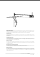
GDO-7v2 Overhead Garage Door Opener INSTALLATION INSTRUCTIONS | OWNERS COPY
WARNING: It is vital for the safety of persons to follow all instructions. Failure to comply with the installation instructions and the safety warnings may result in serious personal injury and/or property and remote control opener damage. Please save these instructions for future reference.
Dominator® GDO-7v2 Overhead Garage Door Opener Important Safety Instructions Features Operating Controls Package Contents Installation C-Rail Assembly Determine the Door Type Mounting on a Track Type Door Mounting on a non-Track Type Door Mounting Door Bracket & Arms Programming the Opener Setting Limits Setting Limits: via Transmitter Safety Obstruction Force Safety Obstruction Force Test Adjustin Safety Obstruction Forces Coding Transmitters Door Courtesy Light Vacation Mode Pet (Pedestrian)Mode Remotely
Important Safety Instructions WARNING: It is vital for the safety of persons to follow all instructions. Failure to comply with the following Safety Rules may result in serious personal injury and/or property damage. CAUTION: If your garage has no pedestrian entrance door, an emergency access device should be installed. This accessory allows manual operation of the garage door from outside in case of power failure. For ADDITIONAL SAFETY protection we STRONGLY recommend the fitting of a Photo Electric (P.E.
Important Safety Instructions The unit should be installed so that it is protected from the elements. It should not be exposed to water or rain. It is not to be immersed in water or sprayed directly by a hose or other device. The garage door must be well balanced. Sticking or binding doors must be repaired by a qualified garage door installer prior to installation of the opener. Frequently examine the installation, in particular cables, springs and mountings for signs of wear, damage or imbalance.
Features Thank you for purchasing the Dominator® GDO7v2 Automatic Garage Door Opener. Designed by our renowned engineers to suit sectional overhead and one piece tilt up doors, the GDO-7v2 will provide years of secure convenience to your home. Operation To open or close the door simply press a button on a TrioCode™ handheld transmitter, a wall mounted transmitter, or optional wall switch for two seconds. During open and close cycles the door can be stopped by pressing the button again.
Auto courtesy light The GDO-7v2 courtesy light comes on automatically whenever the door is activated. The light can also be switched on and off without operating the door by coding a dedicated button on a TrioCode™ transmitter. The light will stay on for approximately three minutes then switch off. This time is adjustable. Vacation mode A hand held transmitter can be programmed to lock and unlock all other transmitters that have been programmed into the openers’ memory.
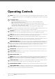
Operating Controls 01 02 PROG (Input) is used to connect he Automatic Technology Handheld Programmer PG-3 for editing control and receiver functions, accessing diagnostic, and activating special features and operating modes. Terminal Block (J6). • • • • 30V PWR is used to power devices such as: Photo electric beam (PE-2) for safety and auto-close function (P.E. and P.E.(0V) terminals). GND - Common ground for accessories. OSC is used for the connection of a wired switch (momentary contact).
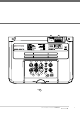
01 02 J4 0800 366462 04 03 08 05 10 09 12 11 06 13 07 15 14 fig 01 Owner Installation Instructions Dominator® 9
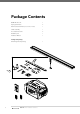
Package Contents GDO-7V2 drive unit 1 Keyring transmitters 2 Wall mounted transmitters (not available all models) 1 Shuttle assembly 1 Door attachment arms 2 Hardware pack 1 Installation Manual 1 Packaged Seperately C-Rail Kit (packed seperately) fig 02 10 GDO-7v2 Owner Installation Instructions 1
C-Rail Assembly IMPORTANT SAFETY INSTRUCTIONS FOR INSTALLATION Warning: Incorrect installation can lead to severe injury. Follow ALL installation instructions. Step 1 - Connect the Powerhead to the CRail Locate and insert the powerhead’s shaft into the C-Rail’s sprocket as shown in (Fig. 03). fig 03 Step 2 - Secure the C-Rail Fix the two track brackets as shown in (Fig. 04). Fix with the four screws supplied in accessory pack.
Determine the Door Type Step 3 - Determine Door Type Determine which type of garage door you have as illustrated below. (Fig. 05 to 07). For a sectional (panel) door on tracks (Fig. 05) proceed with the installation from Step 5. Track fig 05 Door Sectional door with track For a one-piece door on tracks (Fig. 06) proceed with the installation from Step 5. fig 06 One piece door with track For a one-piece door without tracks (on springs) (Fig. 07) proceed with the installation from Step 9.
Mounting on a Track Type Door Step 4 - Determine Bracket Position a. b. c. Open the door and find the highest point of travel of the top door panel. Using a level, transfer this height to the wall above the door (Fig. 08) and mark a line 60mm above it. Determine the centre point on the wall above and on top of the door. Draw two lines extending 21.5mm from each side of the centre point. (Fig. 09) Level Level Track Track fig 08 Door Door Step 5 - Mounting the Wall Bracket a. b. c.
Mounting on a non-Track Type Door WARNING: Make sure concrete, brick wall or timber lintels are solid and sound so as to form a secure mounting platform. Centre of Door Step 8 - Determine the Door’s Centre fig 12 a. b. Find the centre of the door and mark this location both above the door and on top of the door. Draw two lines 21.5mm either side of this (Fig. 12). Step 9 - Prepositioning the Opener a. b. c. Raise the door to open position.
Mounting Door Bracket & Arms Step 12 - Mounting Door Bracket The door bracket comes in two parts. The bottom plate with two mounting holes is used on its own for one piece doors. For sectional doors, the top plate is placed over the bottom plate and is fixed with four (4) screws (Fig. 16). a. b. fig 16 Mount the door bracket, or bracket assembly, on the door’s centre line one-third down the top panel (Fig. 16) using M6 or equivalent screws (not supplied), STEEL DOORS ONLY: Bracket can be welded in place.
Setting Limits NOTE: If P.E. Beams are to be used they must be installed before setting the travel limits. Step 14 - Remove Controls Cover Remove the controls cover to access the control panel Replace it when setup is completed. fig 20 Step 15.1 - Connect Power to the Powerhead Plug the power cord into a mains point and switch power on. The red CLOSE LIMIT LED will be flashing.
Setting Limits: via Transmitter The GDO-7v2 has the unique ability to set travel limits using the transmitter, allowing the installer to move around the garage and door to better assess the desired close and open limit positions. Step 16.1 - Power Up and Set the Datum fig 22 Follow Steps 15.1 to 15.3 as outlined overleaf. Observe all warnings! a. Step 16.2 - Code a Transmitter for Limit Setting a. b. c. Press and hold the DOOR CODE button (Fig. 22).
Safety Obstruction Force Test WARNING! Take care when testing or adjusting the Safety Obstruction Force. Excessive force may cause SERIOUS PERSONAL INJURY and/or PROPERTY DAMAGE. Step 17.1 - Testing Close Cycle fig 24 a. b. c. Press the OPERATE button to open the door (Fig. 24). Place a piece of timber approximately 40mm high on the floor directly under the door (Fig. 25). Press the OPERATE button to close door. The door should strike the object and start to re-open. Step 17.2 - Testing Open Cycle a. b.
Adjusting Safety Obstruction Forces Adjusting Safety Obstruction Force The Safety Obstruction Force is calculated automatically during setup. Adjusting this is normally only necessitated by environmental conditions such as windy or dusty areas, and areas with extreme temperature changes. fig 26 WARNING: Doors that exert more than 400N (40kgf) closing force must have a Photo Electric Beam (P.E.Beam, Model: PE-2) fitted for safety. a. b. c. d. Step 18.
Coding Transmitters Step 19.1 - Code a Transmitter Button for Door Operation a. b. c. d. fig 27 Press and hold the DOOR CODE button (Fig. 27). Press one of the four buttons on the transmitter for two (2) seconds, pause for two (2) seconds, then press the same button again for two (2) seconds. Release the DOOR CODE BUTTON. Press the transmitter button to test. Step 19.
Coding Transmitters Step 20 - Remotely Coding Transmitters Using this method transmitters can be coded without access to the opener’s control panel as long as a precoded transmitter is available. Coding hole IMPORTANT NOTE: The door or courtesy light must activate when the steps below are performed. This indicates that the pre-coded transmitter is in range of the opener, and the correct button has been pressed. a. b. c. d. e. Take any pre-coded transmitter.
P.E. Beams & Auto-close RECEIVER 12V 12V 24V 24V 1 2 3 4 5 fig Step 22 - Fitting the P.E. Beams (optional) TRANSMITTER Affix the P.E. Beams (PE-2) in a strategic location within the doorway. We recommend 150mm above the floor level and as close as possible to the door opening, inside the garage. b. Connect the PE-2 (Order Code 90214) and the P.E.Beam Interface Kit V2 (Order Code 01901) to the Opener in accordance with (Fig.32). NOTE: Resistor R1 shall be 2.2kOhm, 1/4W.
Final Set Up Step 24 - Setting of Courtesy Light Time The courtesy light time can only be adjusted with the Universal Programmer (PG-3). Step 25 - Setting the Pet Mode position fig 34 The default Pet Mode height can be changed as follows: a. Make sure the door is closed, then press and hold the PLUS (+) button for six (6) seconds (Fig.34) until you hear three beeps and the OPEN and CLOSE LEDs flash rapidly. b. Press the PLUS (+) or MINUS (-) button to move the door to the desired pet mode open position.
Parameters Door Status Indicators Door Opener State OPEN LED (Green) Open On Close Beeper On Opening Flashing Closing Flashing Door travel stopped Flashing Door obstructed when opening Flashing Door obstructed when closing 24 CLOSE LED (Red) Flashing Flashing Opener overloaded Alternating flashes Door in open position with AutoClose mode selected One second flashes Mains power interrupted Rapid flashes GDO-7v2 Owner Installation Instructions Alternating flashes Beeps as door move
Parameters Button Functions Buttons Function OPERATE Opens/Stops/Closes the door DOOR CODE Codes a transmitter button for operate function, Pet, Vacation Modes and AUX functions LIGHT CODE Codes a transmitter button for light function FORCE MARGIN SET & OPEN Increases the obstruction force margin setting FORCE MARGIN SET & CLOSE Decreases the obstruction force margin setting FORCE MARGIN SET (then) SET Resets the factory default force margin settings AUTO CLOSE TIME (then) OPEN Increases the
Default Settings & Specifications Factory Default Settings Default Step Maximum Maximum motor run time 30 sec - - Courtesy light time 4 min - - Obstruction force margin 2 1 26 Auto close time 0 secs 1 4 min Technical Specifications Power supply 230 - 240Va.c., 50Hz Standby power 2.2 Watts Motor power 250 Watts (1/3 HP) Motor type Alternating Current Shuttle travel distance * 2.7m approx. (Standard) Maximum shuttle travel distance in the C-Rail * 3.
Troubleshooting Symptom Door will not operate Possible cause Remedy Mains power not switched on. Switch on mains power. Door is obstructed. Remove obstruction. Door is locked or motor jammed. Unlock door or remove jam. Door tracks/hardware damaged. Door requires service/repair by qualified technician. The opener is in “vacation mode” Turn off “vacation mode”. Adverse weather conditions (wind or cold) causing door to stiffen and become tight in the tracks.
Maintenance Maintenance Yearly The SERVICE LED will indicate the requirement for a service and/or adjustment. To reset the SERVICE LED when the door is serviced, reprogram the Door Travel Limits and the Door Travel Force – on completion of this programming the SERVICE LED will go out. Dominator® suggests you contact your installer to perform an annual door service. Whilst your opener does not require any periodic maintenance, the door that it is fitted to does.
Spare Parts Owner Installation Instructions Dominator® 29
Warranty and Exclusion of Liability 1. This warranty is an addition to any non-excludable conditions or warranties that are implied into this contract by relevant statutes. 2.
Owner Installation Instructions Dominator® 31
© January 2008 B&D Doors (NZ) Limited. All rights reserved. No part of this document may be reproduced without prior permission. In an ongoing commitment to product quality we reserve the right to change specification without notice. E&OE.