LCD TELEVISION INSTRUCTION MANUAL DLN-15D3SHS DLN-17D3SHS DLN-20D3AHS
IMPORTANT INFORMATION CAUTION RISK OF ELECTRIC SHOCK DO NOT OPEN CAUTION : TO REDUCE THE RISK OF ELECTRIC SHOCK, DO NOT REMOVE COVER (OR BACK) NO USER-SERVICEABLE PARTS INSIDE. REFER SERVICING TO QUALIFIED SERVICE PERSONNEL. The lightning flash with arrowhead symbol, within an equilateral triangle, is intended to alert the user to the presence of uninsulated “dangerous voltage” within the product’s enclosure that may be of sufficient magnitude to constitute a risk electric shock.
IMPORTANT INFORMATION WARNING : FCC regulations state that any unauthorized changes or modifications to this equipment not expressly approved by the manufacturer could void the user’s authority to operate this equipment. U.S.A.
SAFETY PRECAUTIONS The present set has been designed and manufactured to assure personal safety. Improper use can result in electric shock or fire hazard. The safeguards incorporated in the present unit will protect you if you observe the following procedures in installing, using and servicing. The present unit is fully transistorized and does not contain any element that can be repaired by the user. • Influx of objects and liquids : Never let objects into the productthrough vents or openings.
SAFETY PRECAUTIONS • Replacement parts : In case the product needs certain parts to be replaced, make sure that the service engineer uses the replacement elements either specified by the manufacturer, or with the same characteristics and performance as original ones. Using unauthorized parts can result in fire, electric shock and/or other danger. • Stand : Do not place the product on an unstable cart, stand, tripod or table.
SAFETY PRECAUTIONS • As a measure of additional protection of this television equipment, unplug this apparatus during lightning storms or when unused for long periods of time. This will prevent the equipment from being damaged by lightning and power-line surges. • Outside antenna system should not be located in the vicinity of overhead power lines or other electric or power circuits including the place where it can fall onto such power lines or circuits.
CONTENTS IMPORTANT SAFEGUARDS 5 SUPPLIED ACCESSORIES 6 FUNCTIONAL OVERVIEW Front (Control panel) Remote controller 7 7 8 PREPARATION Inserting Batteries into the Remote Control Unit Mains connection Aerial connection Connecting external equipment 9 9 9 10 12 INSTALLATION Language selection Automatic Tuning of TV Channels Programme Editing Manual Setup 15 15 15 16 17 DAILY USE Switching On and Off Recall Programme Selection Picture Control Sound Control Special Features Sleep Teletext (Option) PC s
Supplied Accessories AC cord AC adapter POWER PR VOL VOL MENU PC PR 1 2 4 5 7 8 SLEEP 3 6 9 NORMAL 0 RECALL ASPECT S.
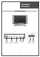
Functional Overview Front (Control panel) STAND-BY ON/OFF CH VOL Power On/Off CH Up/Down Volume Up/Down TV/VIDEO MENU AV MENU 9 Remote sensor LED indicator
Functional Overview Remote Controller [ ] : Teletext function POWER MUTE MUTE MUTE CH CH UP MENU VOL VOL MENU LEFT(VOLUME DOWN) RIGHT(VOLUME UP) DISPLAY DISPLAY TV NUMBER(PAGE) MTS CH PC AV COMPONENT 1 2 3 4 5 6 7 8 CH DOWN 9 PREV. CH 100 0 PREV.
Preparation Inserting Batteries into the Remote Control Unit To load the batteries, turn the remote control handset over and open the battery compartment. Insert the batteries (Not supplied, two 1.5v, type R03 or AAA). Make sure that the polarity matches with the (+) and (-) marks inside of the battery compartment. Note: To avoid damage from possible battery leakage, remove the batteries if you do not plan to use the remote control handset for an extended period of time. Mains Connection 1.
Connections ANTENNA CONNECTION TO CABLE TV (CATV) Cable TV Converter/Descrambler Incoming cable RF Switch Two-set signal SPLITTER • A 75-ohm coaxial cable connector is built into the set for easy hookup. When connecting the 75-ohm coaxial cable to the set, screw the 75-ohm cable to the ANT. terminal. • Some cable TV companies offer “premium pay channels”.
Connections TO WALL ANTENNA SOCKET If there is a wall antenna socket in apartment house, connect the antenna cable as shown below. (Use the type of antenna cable corresponding to that of wall antenna socket.) Wall connecting port 75 300 round cable Turn clockwise to tighten flat cable Antenna converter For good quality of image, the antenna requirements of color television reception are more strict than those of black & white television reception.
Connections TO OUTDOOR ANTENNA This type of antenna is usually used at common private house. Combination VHF/UHF Antenna 75 300 round cable flat cable Turn clockwise to tighten Antenna converter UHF VHF Signal Amplifier • Use one of the two following diagrams if you connect an outdoor antenna. A : Using a VHF/UHF combination outdoor antenna. B : Using separate VHF and/or UHF outdoor antennas. • Connect the outdoor antenna cable lead-in to the ANT IN on the back of TV set.
Connections Connecting external equipment COMPONENT 2 COMPONENT 1 PC INPUT Pr Pb Pb R L Y Y R S-VIDEO L Pr L R Y R Pb AUDIO Pr VIDEO DC PC POWER AUDIO L Headphone S-video cable PC DVD DTV Set Top Box 15 VCR/Camcorder/ Video Game
Connections You can enjoy picture and sound by connecting VCR, DVD player (or DTV Set-Top Box) and PC to the terminals located on the back of TV set. Before connecting an external device, turn the TV set off to avoid any possible damage. DVD or DTV Set-Top Box input terminal [COMPONENT IN] These jacks have Y/Pb(Cb)/Pr(Cr) inputs and AUDIO inputs. These jacks are used to connect a DVD player, DTV Set-Top Box.
Basic Operations SWITCHING ON/OFF SWITCHING ON 1 If the indicator is not lit, the TV set is powered off. You must press the POWER button of the TV set. 2 Press the POWER button on the remote controller on the TV set when the indicator is red. The TV set will be switched on and the indicator will be changed to green. SWITCHING OFF 1 To set the TV set back to stand-by mode, press the POWER button on the remote controller on the TV set for 2 seconds. The indicator will become red.
Basic Operations VOLUME CONTROL Adjust the volume with VOL ( ) buttons. VOL TO MUTE THE SOUND Press the MUTE button on the remote controller to cut the sound off. By pressing either the MUTE button or VOL ( ) buttons, you can get sound back. VOL MUTE CHANNEL SELECTION The TV set has 68 channels [AIR02 ~ AIR69] in AIR mode and 125 channels [CATV01 ~ CATV125] in CATV mode. (Refer to next page for each selection.) DIRECT SELECTION The numeric buttons are used for direct channel selection.
Menu Adjustment CHANNEL ADJUSTMENT (ONLY IN TV MODE) Press MENU button to display the MENU screen. Press VOL up( ) button to enter into the items below. The color of selected items becomes blue. AIR/CABLE SELECTION 1 Move to “AIR/CABLE” by pressing CH ( ) buttons. 2 Press VOL ( ) buttons to select either AIR or CABLE which is appropriate to your antenna system. Picture Sound ADD OR DELETE CHANNEL You can add additional channels or erase unwanted channels from TV memory.
Menu Adjustment PICTURE ADJUSTMENT Press MENU button to display the MENU screen. Select “PICTURE” by pressing VOL ( ) buttons and press CH down ( ) button to enter into below items. CONTRAST ) buttons. 1 Move to “CONTRAST” by pressing CH ( 2 Press VOL ( ) buttons to adjust the picture contrast. For less contrast For more brightness COLOR 1 Move to “COLOR” by pressing CH ( ) buttons. 2 Press VOL ( ) buttons to adjust color intensity.
Menu Adjustment SOUND ADJUSTMENT Press MENU button to display the MENU screen. Select “SOUND” by pressing VOL ( ) buttons, then press CH down ( ) button to enter into the items below. Picture Sound For weaker treble For stronger treble BASS 1 Move to “BASS” by pressing CH ( ) buttons. 2 Press VOL ( ) buttons to adjust the bass weaker or stronger. For weaker bass For stronger bass BALANCE 1 Move to “BALANCE” by pressing CH ( ) buttons.
Menu Adjustment Daily Use PC ADJUSTMENT (ONLY IN PC MODE) PC Mode input format. Standard Resolution(Mode) V-frequency(Hz) H-frequency(Hz) MAC IBM VESA 15” 17” 20” 640x480 66 35.00 O O O 832x624 75 49.73 O O O 640x480 60 31.47 O O O 720x400 70 31.47 O O O 640x480(VGA) 72 37.86 O O O 800x600(SVGA) 60 37.88 O O O 72 48.08 O O O 60 48.37 O O X 70 56.48 O O X 60 47.
Menu Adjustment Daily Use Before adjustment, please setup your PC software... Even if your actual display-settings screen looks different from the windows below, basic setup methods will be applied in most of the cases. 1 First, click on “Settings” on the Windows Start menu. While “Settings” is selected, move the cursor to submenu “Control Panel”. 2 When the control panel screen appears, click on “Display” and a display dialog box will appear. 3 Navigate to the “Settings” tab on the display dialog-box.
Menu Adjustment Press MENU button to display the MENU screen. Select “PC” by pressing VOL ( ) buttons and press CH down ( ) button to enter into the items below. Picture H position 100 V position Sound 0 Phase 11 Frequency Utilities 0 Auto setup Screen H-POSITION 1 Move to “H-POSITION” by pressing CH ( buttons. 2 Press VOL ( ) buttons to adjust the horizontal position of displayed image. ) V-POSITION 1 Move to “V-POSITION” by pressing CH ( ) buttons.
Wall/Arm Mounting Attaching a Wall or Arm mounting device This TV supports the VESA mounting standard and willaccommodate various VESA mounting devices. To install any VESA mounting device, please follow the manufacturer’s instructions. 1. Remove all cables connected to the TV. 2. Lay the LCD TV face-down on a flat surface with ablanket or other soft materials to protect the screen. 3. Remove the four screws attaching the stand. Remove stand from LCD TV. 4. Remove the four screws attaching the VESA. 5.
SPECIFICATION MODEL NUMBER DLN-15D3SHS DLN-17D3SHS POWER REQUIREMENT AC 100V-240V~, 50/60Hz POWER CONSUMPTION 34W DLN-20D3AHS 40W 50W APPEARANCE(mm) 463x345x215 544x358x215 608x456x215 WEIGHT 6Kg 7Kg 11Kg SCREEN SIZE 381mm 434.38mm 510.54mm ASPECT RATIO 4:3 16:9 4:3 NUMBER OF PIXELS 1024x768 1280x768 800x600 DISPLAY COLOR 16.2M 16.2M 8bit 16.7M 8bit PIXEL PITCH 0.3(H)x0.3(V) 0.29(H)x0.29(V) 0.51(H)x0.