
User's Manual


6
NOTE:If you need to re move or replace the tra nsmit ter ba tter y,
do not pu ll on its wires t o remove it.I nstead,ge ntly pull on
the con nector's pl astic housi ng where it plu gs into the tra nsmitter.
CAUTION
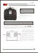
The module is unre mo vable which i s fixed to
the product.
RF modu le
Train er function
/DSC fu nction conn ector
Batte ry cover
Carry ing Handle
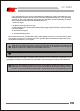
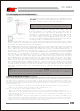
Stick l ever tensio n adjustmen t:
Yo u ma y ch ang e th e le ngt h of the con tro l st ick s to mak e yo ur t ran smi tte r mo re c omf ort ab l e t o
ho ld an d o pe r at e .T o l eng the n or sho rt e n you t t ra nsm itt er' s s ti c ks ,fi rst un loc k the s t ic k t ip
by h ol d in g l oc k in g scr ew B an d urn ing s tic k tip A c oun te r cl o ck w is e. Ne xt, mov e the l ock ing s cre w
B u p or d own (to len gth en o r sh r ot e n) .Wh en th e le ngt h fe els com for tab le, loc k th e po sit ion b y
tu rn i ng l o ck i ng s cre w B cou nte rcl ock wis e.
SCREW B STICK TIP A
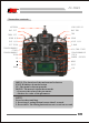
RUDDER
ELEVATOR
AILERON
Mode 1 transmitter with rear cover removed.
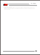
Yo u ma y ad ju st th e te ns io n of yo ut st ic ks
to pr ov id e th e fe el th at yo u pr ef er fo r
fl yi ng .To ad ju st yo ut sp ri ng s ,yo u 'll ha ve
to re mo ve th e re ar ca se of th e tr an sm it te r.
Fi rs t,us in g a sc re wd ri ve r, re mo ve th e si x
sc re ws th at ho ld th e tr an sm it te r' s re ar
co ve r in jp os it io n ,an d pt th em in a sa fe
pl ac e.Ge nt ly ea se of f th e tr an sm it te r' s
re ar co ve r. No w yo u' ll se e th e vi ew sh ow n
in th e fi gu re ab ov e .
Us in g a s ma l l ph i ll ips s cre wdr ive r,r ota te
th e ad ju s ti n g sc re w fo r ea ch s t ic k fo r th e
de si r ed sp rin g ten sio n.T he ten si o n inc rea ses
wh en t h e ad j us t in g scr ew in t urn ed cl ock wis e.
Wh en y o u ar e s at i sf ied w ith t he sp rin g ten sio ns,
re at t ac h th e tran smi tt e r' s re ar cov er. Ch e ck
th at th e upper PCB is on its loca tin g pin s,
re in s ta l l the re ar c ove r and tig hte n the si x
sc re w s.
FS-TH9X