Installation Manual (Pages 1-19) IP VIDEO DOOR STATION D10x Series Installationsanleitung (Seite 20-39) IP VIDEO TÜRSTATION D10x Series Manuel d´installation (Page 40-57) INTERPHONE VIDÉO IP D10x Série Manuale di installazione (Pagina 58-67) VIDEOCITOFONO IP D10x Series Manual de Instalación (Página 68-85) VIDEOPORTERO IP D10x Series VERSION 1.9, MIN. HW 1.
INSTALLATION MANUAL Read these instructions carefully before starting to use any components. Keep the manual so you can refer to it at a later date if required. If you hand over the device to other persons for use, please hand over the operating manual as well. You can always find the most up-to-date version of the installation manual on www.doorbird.com/support To make things easier we use the term “device” for the product “IP Video Door Station” and “mobile device” for a smartphone or tablet.
Notice: Indicates a situation which, if not avoided, could result in damage to property. Important: Indicates significant information which is essential for the product to function correctly. ENGLISH N OTI C E Note: Indicates useful information which helps in getting the most out of the product. Hazard information WARNING ∙ Mounting, installation and servicing work on electrical devices may only be performed by a qualified eletrician.
WARNING ∙ For safety, approval and licensing reasons (CE/FCC/IC etc.), unauthorized change and/or modification of the device is not permitted. ∙ The device is not a toy; do not allow children to play with it. Do not leave packaging material lying around. Plastic films/bags, pieces of polystyrene, etc. can be dangerous in the hands of a child. ∙ Always lay cables in such a way that they do not become a risk to people and domestic animals. ∙ Voltage is applied to parts within the equipment.
∙ Existing wiring such as chime wiring, etc. may contain high voltage AC electricity. Damage to the device or electric shock could result. Wiring and installation must be done by a qualified eletrician. ENGLISH ∙ Do not put any metal or flammable material into the device. Fire, electric shock, or device trouble could result. ∙ When mounting the device on a wall or ceiling, install the device in a convenient location, but not where it could be jarred or bumped. Injury could result.
WARNING ∙ On devices with intercom, be sure to perform a call test with low audio volume on both intercom devices. A sudden call etc. may arrive causing for example damage to your ear. ∙ If the device does not operate properly, unplug the power supply. ∙ All devices which are not marked as weather-proof are designed for indoor use only. Do not use outdoor. ∙ On devices which are marked weather-proof: Do not spray with high-pressure water. Device issues could result.
∙ On devices with intercom or built-in speaker or built-in microphone or signal transmission functions, keep the wires more than 30 cm (12'') away from AC 100-240 V wiring. AC induced noise and/or device malfunction could result. ENGLISH ∙ Keep the device more than 1 m (3.3') away from microwave, radio, TV, wireless router and any other wireless devices. ∙ Install the device in an area that will be accessible for future inspections, repairs and maintenance.
Transportation N OTI C E When transporting the device, use the original packaging or equivalent to prevent damage to the device. Warranty Information For information about the device warranty, see www.doorbird.
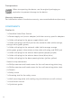
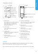
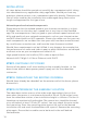
front 1 Night vision back 8 Locking positions ENGLISH Video door station 2 HDTV video 3 Loudspeaker 4 Motion sensor 5 Stainless-Steel Button 9 Connection terminal 6 Microphone 7 Light sensor 10 Screw opening 1) Night vision 5) Stainless-Steel Button Extra bright infra-red LEDs, effective With illuminated LED ring (at night), during the hours of darkness also acts as Diagnostic-LED (infra-red light invisible to the 6) Microphone human eye, 850 nm) With active noise cancellation 2) HDTV video 7) Ligh
INSTALLATION All steps below should be carried out carefully by a competent adult, taking into consideration any applicable safety regulations. Should you have any questions, please contact us or a competent specialist directly. Please ensure that all wires used for the installation are undamaged along their entire length and approved for this type of use. Network speed and network components Please ensure that the upload speed of your Internet connection is at least 0.5 Mbps.
Do not expose the device to direct sunlight. The housing temperature can exceed the maximum allowed temperature limit. This can result in damage of electric and mechanic components of the device and injuries especially when touching exterior parts of the device. White and bright silver-colored front plates absorb less sunlight than dark ones. ENGLISH N OTI C E An image sensor must not be exposed to direct sunlight for an N OTI C E extended period of time.
Power supply via PoE (as an alternative) To power the video door station via a PoE switch (e.g. D-Link DGS-1008P) or PoE injector (e.g. TP-Link TL-PoE150S) in accordance with the PoE standard IEEE 802.3af Mode A, the four wires bearing the numbers 1, 2, 3 and 6 of a Cat.5 cable or better are to be used. A Cat.5 cable or better must be used as network signals can only be transmitted over completely insulated, shielded and twisted cables.
Conventional electric door chime If someone rings your video door station, you will immediately receive a push notification with sound/vibration on your smartphone or tablet. In addition the video door station comes with a zero-potential relay contact for connecting a conventional electric door chime inside the building. The relay contact can be used to activate the separate operating voltage of the door chime or the door chime via its trigger input.
STEP 6: DOWELS If the exterior wall of the house is not made of wood, you should drill four holes 5 mm in diameter in the wall and then place the dowels provided into the boreholes. If the exterior wall of the house is made of wood, you will usually not require any dowels. There are special dowels for assembling the video door station on an insulating wall, e.g. Fischer insulating dowels. Please check with your insulating material manufacturer regarding which dowels they recommend.
V DC, 1 A 0 V, 0 A max. 0 -24 V DC/AC, 1 A max.
STEP 10: FINAL ASSEMBLY Mount the video door station on the mounting plate. The video door station will click into the locking positions intended for the mounting plate. Use the accompanying safety screw with the appropriate tool to fix the video door station to the underside of the mounting plate. STEP 11: ACTIVATING THE VIDEO DOOR STATION Switch on the power to the wires leading to the assembly location again.
After around two to five minutes, the video door station emits brief diagnostic sounds after it has been connected to the power grid.
AUDIO Audio components: Speaker and microphone, echo and noise cancellation Audio streaming: Two-way duplex NETWORK WiFi: 802.11 b/g/n 2.4 GHz Ethernet: Connector, PoE 802.3af Mode-A MOTION SENSOR Type: Passiv infrared sensor (PIR) Detection angle: 180° Range: 2 - 8 m (79 - 315 in) depends on environment INTEGRATED WIRELESS MODULES WiFi: 2,4 GHz, internal antenna OPTIONAL ACCESSORIES Sold separately: see www.doorbird.com/buy LEGAL NOTES General remarks 1.
In many countries video and voice signal may only be transmitted once a visitor has rung the bell (data privacy, configurable in the App). · Please carry out the mounting in such a way that the detection range of the camera limits the device exclusively to the immediate entrance area. · The device may come with a visitor history and motion sensor. You can activate/deactivate this function if required. If necessary, indicate the presence of the device in a suitable place and in a suitable form.
INSTALLATIONSANLEITUNG Lesen Sie diese Anleitung sorgfältig, bevor Sie die Komponenten in Betrieb nehmen. Bewahren Sie die Anleitung zum späteren Nachschlagen auf! Wenn Sie das Gerät anderen Personen zur Nutzung überlassen, übergeben Sie auch diese Bedienungsanleitung. Die stets aktuelle Version der Installationsanleitung finden Sie unter www.doorbird.com/de/support Zur Vereinfachung der Begriffe verwenden wir „Gerät“ für das Produkt „IP Video Türstation“ sowie „mobiles Endgerät“ für ein Smartphone/Tablet.
Vorsicht: Weist auf eine gefährliche Situation hin, welche, falls nicht verhindert, zu geringfügiger oder mäßiger Verletzung führen kann. N OTI C E Bitte beachten: Weist auf eine gefährliche Situation hin, welche, falls nicht verhindert, zu Sachschäden führen kann. Wichtig: Weist auf wichtige Informationen hin, die den richtigen Betrieb des Produkts gewährleisten. DEUTSCH Hinweis: Weist auf nützliche Informationen hin, die die optimale Verwendung des Geräts unterstützen.
WARNUNG ∙ Öffnen Sie das Gerät nicht. In solchen Fällen erlischt jeder Gewährleistungsanspruch! Für Folgeschäden übernehmen wir keine Haftung! Das Gerät enthält keine durch den Anwender zu wartenden Teile. Im Fehlerfall lassen Sie das Gerät von einer autorisierten Fachkraft prüfen. ∙ Aus Sicherheits-, Zulassungs- und Lizenzgründen (CE/FCC/IC etc.) ist das eigenmächtige Umbauen und/oder Verändern des Gerätes nicht gestattet. ∙ Das Gerät ist kein Spielzeug! Erlauben Sie Kindern nicht damit zu spielen.
∙ Schließen Sie keinen Anschluss am Gerät an eine Netzstromleitung an. Feuer oder elektrische Stromschläge können die Folge sein. ∙ Stellen Sie sicher, dass das Netzkabel nicht beschädigt oder gequetscht ist. Wenn das Netzkabel gebrochen ist, kann es zu einem Brand oder elektrischen Stromschlag kommen. ∙ Nichts mit nassen Händen anstecken oder abziehen. Elektrische Stromschläge können die Folge sein. DEUTSCH ∙ Führen Sie kein Metall oder brennbares Material in das Gerät.
WARNUNG - Orte mit Staub, Öl, Chemikalien, Schwefelwasserstoff (heiße Quellen). - Orte, die extremer Feuchtigkeit und Luftfeuchtigkeit ausgesetzt sind, wie Bäder, Keller, Gewächshäuser, etc. - Orte, an denen die Temperatur extrem niedrig ist, wie z. B. in einem gekühlten Bereich oder vor einer Klimaanlage. - Orte, die Dampf oder Rauch ausgesetzt sind (z.B. in der Nähe von Heiz- oder Kochflächen).
∙ Achten Sie darauf, dass das Gerät weder Stößen noch starkem Druck ausgesetzt ist. ∙ Installieren Sie das Gerät nicht an instabilen Halterungen, Oberflächen oder Wänden. Stellen Sie sicher, dass das Material stabil genug ist, um das Gewicht des Geräts zu tragen. ∙ Verwenden Sie keine chemischen, ätzenden oder aerosolhaltigen Reinigungsmittel. DEUTSCH ∙ Verwenden Sie bei der Installation des Geräts ausschließlich passende Werkzeuge. Ein zu großer Kraftaufwand mit Werkzeugen kann das Gerät beschädigen.
N OT I C E ∙ Das Gerät wird während eines Stromausfalls außer Betrieb gesetzt. ∙ Bei Geräten mit Gegensprechfunktion oder eingebautem Lautsprecher oder eingebautem Mikrofon kann das Gerät in Bereichen, in denen Antennen von Mobilfunksendern, Radio- oder TV-Sendern in der Nähe sind, beeinträchtigt werden.
KOMPONENTEN Inhalt ∙ 1x DoorBird Video Türstation ∙ 1x Steckernetzteil mit vier Landesadaptern ∙ 1x Kabel mit Stecker für die Stromversorgung (schwarz, rot) ∙ 1x Kabel mit Stecker und RJ45 Buchse für das Netzwerkkabel ∙ 1x Kabel mit Stecker für den elektrischen Türöffner (lila, lila) DEUTSCH (weiß-orange, orange, weiß-grün, grün) ∙ 1x Kabel mit Stecker für das Netzwerkkabel (weiß-orange, orange, weiß-grün, grün), als Alternative zum Kabel mit Stecker und RJ45 Buchse ∙ 1x Kabel mit Stecker für den elektri
Video Türstation Vorderseite 1 Nachtsicht Rückseite 8 Einrastpunkte 2 HDTV Video 3 Lautsprecher 4 Bewegungssensor 5 Edelstahl Button 9 Anschlussterminal 6 Mikrofon 7 Lichtsensor 1) Nachtsicht Superhelle Infrarot-LEDs, sind im Dunklen aktiv (für Menschen unsichtbares Infrarotlicht, 850nm) 2) HDTV Video Hemispherische UltraweitwinkelLinse, 180° 3) Lautsprecher Großer und sprachoptimierter Breitbandlautsprecher 4) Bewegungssensor 180° Infrarot Bewegungssensor für Alarmierung 10 Schrauböffnung 6) Mikrofo
INSTALLATION Alle folgenden Schritte sollten von einem fachkundigen Erwachsenen sorgsam und unter Berücksichtigung sämtlicher geltender Schutzvorschriften durchgeführt werden. Sollten Sie Fragen haben, wenden Sie sich bitte direkt an uns oder einen kompetenten Fachmann. Achten Sie darauf, dass alle Drähte, die Sie für die Installation verwenden, über die gesamte Länge unbeschädigt und für die Verwendungsart zugelassen sind.
N OTI C E N OTI C E Setzen Sie das Gerät keinem direktem Sonnenlicht aus. Die Gehäuse temperatur kann die maximal zulässige Temperaturgrenze überschreiten. Dies kann zu Beschädigungen elektrischer und mechanischer Komponenten des Geräts und zu Verletzungen führen, insbesondere bei der Berührung von Außenteilen des Geräts. Weiße und helle silberfarbene Frontblenden absorbieren weniger Sonnenlicht als dunkle. Ein Bildsensor darf keiner direkten Sonneneinstrahlung über längere Zeit ausgesetzt werden.
1. Trennen Sie den vorgesehenen PoE Switch oder PoE Injektor vom Stromnetz. 2. Führen Sie das Netzwerkkabel zum Montageort der Video Türstation. Kombinieren Sie die Stromversorgung per Steckernetzteil nicht mit der Stromversorgung per PoE. DEUTSCH Stromversorgung per PoE (alternativ!) Zur Stromversorgung der Video Türstation per PoE Switch (z.B. D-Link DGS1008P) oder PoE Injektor (z.B. TP-Link TL-PoE150S) nach PoE Standard IEEE 802.3af Mode A werden die vier Drähte mit den Nummern 1, 2, 3 und 6 eines Cat.
Elektrische Türöffner Die Video Türstation verfügt über einen potentialfreien Relaiskontakt für standardisierte elektrische Tür-, Tor- oder Garagenöffner (zwei Drähte). Es besteht die Möglichkeit, alle elektrischen Türöffner anzuschließen, die im Spannungsbereich bis 24 V (AC/DC) bei einem max. Strom von 1 A arbeiten. Die Video Türstation liefert keine Spannungsversorgung, dies erfolgt durch die separate Spannungsversorgung des elektrischen Türöffners. Die Spannungsversorgung können Sie der Anleitung bzw.
auf den Kontakt geben. Beispiele für kompatible Türöffnertaster und einen beispielhaften Anschlussplan finden Sie unter: www.doorbird.com/de/support SCHRITT 6: DÜBEL SCHRITT 7: MONTAGEPLATTE ANSCHRAUBEN DEUTSCH Wenn es sich bei dem Material der Hauswand nicht um Holz handelt, bohren Sie vier Löcher mit einem Bohrer mit 5 mm Durchmesser in die Hauswand und stecken Sie dann die mitgelieferten Dübel in die Bohrlöcher. Wenn es sich bei der Hauswand um Holz handelt, benötigen Sie im Normalfall keine Dübel.
ANSCHLUSS 15 V DC, 1 A 0 V, 0 A max. 0 -24 V DC/AC, 1 A max.
SCHRITT 10: ENDMONTAGE Montieren Sie die Video Türstation an der Montageplatte. Die Video Türstation rastet an den für die Montageplatte vorgesehenen Einrastpunkten ein. Nutzen Sie die beiliegende Sicherheitsschraube und das dazu passende SchraubTool, um die Video Türstation an der Unterseite mit der Montageplatte zu fixieren. SCHRITT 11: INBETRIEBNAHME DEUTSCH Schalten Sie den Strom der zum Montageort führenden Leitungen wieder an.
DIAGNOSE-LED Diese LED ist nur fünf Minuten lang beleuchtet, nachdem man die Video Türstation mit Strom versorgt hat (und permanent nachts). Sie leuchtet, sobald man die Video Türstation mit Strom versorgt. ∙ Beleuchtet: Gerät ist mit Strom versorgt DIAGNOSE-TÖNE Die Video Türstation gibt nach etwa zwei bis fünf Minuten kurze Töne zur Diagnose aus, nachdem man sie mit dem Stromnetz verbunden hat.
TECHNISCHE DATEN ALLGEMEINES Stromversorgung: 15 V DC (Netzteil 110 ‐ 240 V AC) oder Power over Ethernet (PoE 802.
INTEGRIERTE FUNKMODULE WLAN: 2,4 GHz, interne Antenne OPTIONALES ZUBEHÖR Separat erhältlich: siehe www.doorbird.com/de/buy RECHTLICHE HINWEISE Allgemeines 1. DoorBird ist ein registriertes Warenzeichen der Bird Home Automation GmbH. 2. Apple, das Apple Logo, Mac, Mac OS, Macintosh, iPad, Multi-Touch, iOS, iPhone und iPod touch sind Warenzeichen von Apple Inc. 3. Google, Android und Google Play sind Warenzeichen von Google, Inc. 4. Die Bluetooth® Wortmarke und Logos sind Warenzeichen von Bluetooth SIG, Inc.
In vielen Ländern darf Videobild und Sprache erst dann übertragen werden, wenn ein Besucher geklingelt hat (Datenschutz, konfigurierbar in der App) · Führen Sie die Montage so durch, dass sich der Erfassungsbereich der Kamera ausschließlich auf den unmittelbaren Eingangsbereich beschränkt. · Das Gerät verfügt ggf. über eine integrierte Besucherhistorie und Bewegungssensor. Sie können diese Funktionen, wenn erforderlich, aktivieren/deaktivieren.
MANUEL D’INSTALLATION Lisez soigneusement ce manuel avant de mettre en marche les divers éléments. Conservez ce manuel pour une éventuelle consultation ultérieure ! Si vous transmettez cet appareil à d’autres personnes dans le futur, transmettez-leur également ce manuel. Vous trouverez la toute dernière version du manuel d’installation à l’adresse www.doorbird.
Prudence : indique une situation dangereuse qui, si rien n’est fait pour l’éviter, peut entraîner des lésions légères. N OTI C E Remarque : indique une situation dangereuse qui, si rien n’est fait pour l’éviter, peut entraîner des dommages matériels. Important : indique la présence d’informations importantes garantissant le fonctionnement correct du produit. Indication : indique la présence d’informations utiles en vue de l’utilisation optimale de l’appareil.
MISE EN GARDE ∙ N’ouvrez pas l’appareil. Si vous le faites, votre garantie sera annulée ! L’appareil ne contient aucune pièce pouvant être entretenue par l’utilisateur. En cas d’erreurs, veuillez faire contrôler l’appareil par un spécialiste agréé. ∙ Pour des raisons de sécurité, d’homologation et de licences (CE/FCC /IC etc.), il est interdit de procéder à des transformations et/ou des modifications l‘appareil sans autorisation.
∙ Ne raccordez aucun terminal de l’appareil à une ligne d’alimentation. Il peut en résulter un incendie ou des décharges électriques. ∙ Assurez-vous que le câble d’alimentation ne soit ni endommagé, ni écrasé. Si le câble est rompu, il peut en résulter un incendie ou une décharge électrique. ∙ Ne branchez pas et ne débranchez jamais rien avec les mains mouillées. Cela pourrait provoquer des décharges électriques. ∙ N’introduisez pas de matériaux métalliques ou inflammables dans l’appareil.
MISE EN GARDE dysfonctionnements au niveau de l’appareil : - emplacements exposés à la lumière directe du soleil ou à proximité d’appareils de chauffage dont la température varie. - emplacements exposés à la poussière, à l’huile, aux produits chimiques, à l’acide sulfurique (source chaude). - emplacements soumis à des conditions d‘humidité et d‘humidité extrêmes, tels que des salles de bains, des caves, des serres, etc. - emplacements où la température est très basse, p. ex.
Instructions de sécurité NOT I C E ∙ L‘appareil doit être utilisé conformément aux lois et règlements locaux. ∙ Stocker l‘appareil dans un endroit sec et aéré. ∙ Évitez d‘exposer l‘appareil à des chocs ou à une forte pression. ∙ N’installez pas l’appareil sur des supports, surfaces ou parois instables. Assurez-vous que le matériau utilisé soit suffisamment stable pour supporter le poids de l’appareil. ∙ Lors de l’installation de l’appareil, utilisez uniquement des outils appropriés.
∙ Installez l’appareil dans un endroit accessible en cas d’inspections, de réparations et d’entretiens à venir. ∙ Si l’appareil est utilisé à proximité d’un téléphone mobile, des perturbations peuvent s’ensuivre. ∙ En cas de chute, l’appareil peut être endommagé. Manipulez-le avec prudence. ∙ En cas de panne de courant, l’appareil sera désactivé.
Transport N OTI C E Au besoin, transportez l’appareil dans son emballage d’origine ou dans un emballage adapté, afin d’éviter tout dommage. Garantie Vous trouverez les informations relatives à la garantie en consultant la page www.doorbird.
Interphone vidéo Recto 1 Vision nocturne 2 Vidéo HDTV Verso 8 Point d´ancrage 3 Enceinte 4 Capteur de mouvement 5 Bouton en acier inoxydable 6 Microphone 7 Capteur de lumière 1) Vision nocturne LEDs infrarouges extrêmement lumineuses (pour les personnes lumière infrarouge invisible, 850 nm) 2) Vidéo HDTV Lentille ultra grand-angle hémisphérique, 180 ° 3) Enceinte De grande taille et parole améliorée à large bande 9 Borne de liaison 10 Trous de vis 5) Bouton en acier inoxydable Avec anneau LED lumin
INSTALLATION Toutes les étapes doivent être effectuées par un adulte compétent et en tenant compte de toutes les règles de sécurité applicables. Si vous avez des questions, s‘il vous plaît, appelez-nous directement ou un expert compétent. Assurez-vous que tous les fils que vous utilisez pour l‘installation, sur toute la longueur sont en bon état et approuvé pour l‘utilisation. La vitesse du réseau et de composants de réseau Internet haut débit (fixe): DSL, câble ou fibre Réseau: 802.11b / g / n 2.
ÉTAPE 4: ALIMENTATION L´interphone vidéo peut utiliser l‘adaptateur secteur fourni par l‘intermédiaire de deux fils de sonnette simples ou via PoE (Power over Ethernet) par l‘intermédiaire d‘un câble réseau. En option, l´interphone vidéo peut être alimentée avec un rail DIN, que vous pouvez acheter directement chez nous. L´interphone vidéo n‘a pas de pille comme source d‘alimentation.
1. Débranchez le commutateur PoE fourni ou injecteur PoE du secteur. 2. Faites passer le câble réseau à l‘installation de l´interphone vidéo Ne pas combiner l‘alimentation par adaptateur secteur et l‘alimentation via PoE. ÉTAPE 5: AUTRES CONNEXIONS (EN OPTION!) Faites passer, si vous le souhaitez, des fils supplémentaires pour l‘installation de la interphone vidéo. Les fils ou les options de connexion répertoriée dans cette section sont facultatives.
Sonnette électrique classique Quand quelqu‘un sonne à votre interphone vidéo, vous obtenez un message push avec le son/vibration sur votre smartphone/tablette immédiatement. L´interphone vidéo est également équipée pour la connexion d‘un gong/ carillon de portes électriques classiques à l‘intérieur par l‘intermédiaire d‘un contact de relais sans potentiel.
ÉTAPE 7: VISSEZ LA PLAQUE DE MONTAGE Acheminer les fils que vous souhaitez connecter à l´interphone vidéo, à travers l‘ouverture prévue dans la plaque de montage. Appuyez sur la plaque de montage contre le mur et tourner les vis dans les chevilles ou dans le mur de la maison. L´interphone vidéo et la plaque de montage sont conçues de telle sorte qu’elles peuvent être monté sur des murs irréguliers et donc pas complètement plate.
CONNECTOR DESCRIPTION WIRE T+ Fil blanc-orange, câble réseau (numéro 1, Transmit Data +) blanc-orange, T- Fil orange câble réseau (numéro 2, Transmission de données -) orange R+ Fil blanc-vert du câble réseau (numéro 3, Réception de données +) blanc-vert R- Fil vert du câble réseau (numéro 6, Réception de données -) vert O1 Une gâche électrique (flottant) lilas O2 Une gâche électrique (flottant) lilas C1 Électrique de carillon de porte (flottante) bleu C2 Électrique de carillon de p
Si vous ne pouvez pas entendre le bip, s‘il vous plaît vérifier l‘alimentation et si vous avez utilisé un adaptateur secteur et non-PoE, les pôles positifs et négatifs correctement connectés à l´interphone vidéo. ETAPE 12: LE TÉLÉCHARGEMENT ET L‘INSTALLATION DE L‘APPLICATION Téléchargez l‘application „DoorBird“ de Bird Home automation sur l‘Apple App Store ou Google Play Store sur votre appareil mobile. La dernière version de l‘application du guide est disponible sur www.doorbird.
DONNÉES TECHNIQUES GÉNÉRALITÉS Alimentation électrique : 15 V DC (alimentation 110 - 240 V AC) ou Power over Ethernet (PoE 802.
MODULES SANS FIL INTÉGRÉS ACCESSOIRES OPTIONNELS WiFi : 2,4 GHz, antenne interne Disponibles séparément : voir www.doorbird.com/fr/buy Sous réserve d‘erreurs et d‘omissions. MENTIONS LÉGALES Généralités 1. DoorBird est une marque Bird Home Automation GmbH. déposée de 2. Apple, le logo Apple, Mac, Mac OS, Macintosh, iPad, Multi-Touch, iOS, iPhone et iPod touch sont des marques commerciales d’Apple Inc. 3. Google, Android et Google Play sont des marques commerciales de Google, Inc. 4.
Les mises à jour du logiciel ou du système d‘exploitation (appelées „mises à jour du firmware“) sont normalement installées automatiquement sur les produits de Bird Home Automation GmbH via internet, si cela est techniquement possible. Les mises à jour automatiques du firmware maintiennent les logiciels des produits actualisés afin que ceux-ci fonctionnent toujours de manière fiable, sûre et efficace.
MANUALE DI INSTALLAZIONE È sempre possibile trovare la versione più aggiornata del manuale di installazione su www.doorbird.
Videocitofono frontale 1 Visione notturna 2 Video HDTV parte posteriore 8 Posizioni di bloccaggio 3 Altoparlante 4 Sensore di movimento 5 Pulsante in acciaio inossidabile 6 Microfono 7 Sensore di luce 1) Visione notturna LED infrarossi extra luminosi, efficaci durante le ore di oscurità (luce infrarossa invisibile all‘occhio umano, 850nm) 2) Video HDTV Lente semisferica ultra grandangolare, 180° 3) Altoparlante Altoparlante a banda larga di grandi dimensioni e con voce avanzata 4) Sensore di movimen
INSTALLAZIONE Tutti i passaggi che seguono devono essere eseguiti con cura da un adulto competente, tenendo conto delle norme di sicurezza applicabili. Se avete qualunque domande, contattaci direttamente o uno specialista competente. Assicurarsi che tutti i cavi utilizzati per l‘installazione siano incontaminati lungo tutta la loro lunghezza e siano approvati per questo tipo di utilizzo.
PASSO 4: ALIMENTAZIONE ELETTRICA Il videocitofono può essere alimentata da due semplici fili di campanello utilizzando l‘alimentatore (adattatore di rete) in dotazione o via PoE (Power over Ethernet) utilizzando un cavo di rete. Il videocitofono può anche essere fornita in alternativa con un alimentatore DIN-rail che è possibile ottenere da noi direttamente. Il videocitofono non utilizza la potenza della batteria.
PASSO 5: ULTERIORI CONNESSIONI (OPZIONALE) Se lo si desidera, collegare i cavi aggiuntivi al sito di installazione del videocitofono. I fili o le opzioni di collegamento indicati in questa sezione sono facoltativi. Collegamento dell’unità a una rete È possibile collegare il videocitofono alla rete esistente tramite WiFi o utilizzare alternativamente un cavo di rete (Ethernet).
Convenzionale campanello elettrico Se qualcuno squilla il suo videocitofono, riceverai immediatamente una notifica di spostamento con suono/ vibrazione sul suo smartphone o tablet. Inoltre, il videocitofono è dotata di un contatto a relè a zero potenziale per collegare un normale segnale elettrico della porta all‘interno dell‘edificio.
PASSO 7: FISSARE LA PIASTRA DI MONTAGGIO Inserire i cavi che si desidera collegare al videocitofono attraverso l‘apertura nella piastra di montaggio fornita. Posizionare la piastra di montaggio sulla parete esterna della casa e utilizzare le viti fornite per posizionarla nei tasselli o sulla parete. La piastra di montaggio per il videocitofono è stata progettata in modo tale da poter essere installata anche su pareti irregolari, quindi non è completamente piatta.
CONNETTORE DESCRIZIONE CAVI T+ Cavo di rete bianco e arancione (Numero 1, Trasmissione dati +) bianco-arancio T- Filo cavo a rete arancione (numero 2, dati trasmessi -) arancio R+ Cavo di rete bianco e verde (Numero 3, Ricezione dati +) bianco-verde R- Cavo di rete verde (numero 6, dati di ricezione -) verde O1 Apertura porta elettrica (potenziale zero) viola O2 Apertura porta elettrica (potenziale zero) viola C1 Campanello elettrico (potenziale zero) blu C2 Campanello elettrico (pot
Una volta emessa un suono di diagnosi breve dall‘altoparlante integrato. Questo può durare fino a 5 minuti. Se non si sente un segnale acustico, controllare l‘alimentazione. Verificare anche se avete utilizzato un alimentatore a muro e non PoE e se avete collegato correttamente il polo positivo e il polo negativo al videocitofono.
NOTI LEGALI Revisione generale 1. DoorBird è un marchio registrato di Bird Home Automation GmbH. 2. Apple, il logo Apple, Mac, Mac OS, Macintosh, iPad, Multi-Touch, iOS, iPhone e iPod touch sono marchi di Apple Inc. 3. Google, Android e Google Play sono marchi di fabbrica di Google, Inc. 4. Tutti gli altri nomi di società e prodotti possono essere marchi commerciali delle rispettive società con cui sono associate. 5.
Automation GmbH lo ritiene necessario (ad es. per motivi di protezione dei dati, sicurezza dei dati o stabilità, o per mantenerle aggiornate). Quando è disponibile un aggiornamento del firmware, i server di Bird Home Automation GmbH generalmente lo distribuiscono automaticamente a tutti i prodotti compatibili collegati a Internet o ai server di Bird Home Automation GmbH. Questo processo è graduale e può richiedere diverse settimane.
MANUAL DE INSTALACIÓN Lea atentamente estas instrucciones antes de comenzar a utilizar cualquier producto. Guarde el manual para que pueda consultarlo más adelante si es necesario. Si entraga el producto a otras personas para su uso, por favor, entregue también el manual de instalación para su correcta operación. Encontrará siempre la versión más actualizada del manual de instalación en www.doorbird.
Precaución: Indica una situación peligrosa que, si no se evita, puede resultar en lesiones leves o moderadas. AVISO Aviso: Indica una situación que, si no se evita, podría resultar en daños a la propiedad. Importante: Indica información importante y esencial para que el producto funcione correctamente. Nota: Indica información útil que ayuda a sacar el máximo provecho del producto.
ADVERTENCIA ∙ No abra el dispositivo. Esto anula la garantía del dispositivo. El dispositivo no contiene ninguna pieza que pueda ser manipulada por el usuario. En caso de que se produzca un error, haga revisar el dispositivo por un experto autorizado. ∙ Por razones de seguridad, aprobación y licencia (CE/FCC/IC, etc.), no se permite el cambio y/o modificación no autorizada del dispositivo. ∙ El dispositivo no es un juguete; no permita que los niños jueguen con él.
∙ No conecte ningún terminal del dispositivo a una línea de alimentación de AC. Podría producirse un incendio o una descarga eléctrica. ∙ Evite que el cable de AC se estropee o aplaste. Si el cable de AC está fracturado, podría producirse un incendio o una descarga eléctrica. ∙ No lo conecte o desenchufe con las manos mojadas. Podría resultar una descarga eléctrica. ∙ No introduzca metal o material inflamable en el aparato. Podría ocasionar un incendio, una descarga eléctrica o problemas con el dispositivo.
ADVERTENCIA - Lugares bajo luz solar directa o lugares cercanos a equipos de calefacción que varían en temperatura. - Lugares sujetos a polvo, aceite, productos químicos, sulfuro de hidrógeno (muelles calientes). - Lugares sujetos a condiciones extremas de humedad, como baños, bodegas, invernaderos, etc. - Lugares donde la temperatura es muy baja, como el interior de un área refrigerada o frente a un aire acondicionado. - Lugares sujetos a vapor o humo (p. ej.
∙ Guarde el aparato en un lugar seco y ventilado. ∙ Evite exponer el dispositivo a golpes o presiones elevadas. ∙ No instale el dispositivo en soportes, superficies o paredes inestables. Asegúrese de que el material sea lo suficientemente fuerte como para soportar el peso del dispositivo. ∙ Utilice únicamente las herramientas correspondientes cuando instale el dispositivo. El uso de una fuerza excesiva con las herramientas podría dañar el dispositivo.
AVISO ∙ El dispositivo puede dañarse si se cae. Manipular con cuidado. ∙ El dispositivo se vuelve inoperante durante un corte de corriente. ∙ En los dispositivos con intercomunicador, altavoz incorporado o micrófono incorporado, en áreas donde las antenas de estaciones de radiodifusión celular o de radio/televisión están cerca, el dispositivo puede verse afectado por interferencias de radiofrecuencia.
Información de garantía Para obtener información sobre la garantía del dispositivo, consulte www.door- bird.
Videoportero Parte frontal 1 Visión nocturna 2 Vídeo HDTV Parte posterior 8 Posiciones de fijación 3 Altavoz 4 Sensor de movimiento 5 Botón acero 9 Terminal de 6 Micrófono 10 inoxidable 7 Sensor de luz 1) Visión nocturna LEDs infrarrojos extra brillantes, eficaces durante las horas de oscuridad (luz infrarroja invisible al ojo humano, 850 nm) 2) Vídeo HDTV Lente hemisférica ultra gran angular, 180° 3) Altavoz Altavoz de banda ancha de gran tamaño y voz mejorada 4) Sensor de movimiento Sensor infr
INSTALACIÓN Todos los pasos que se indican a continuación deben ser llevados a cabo cuidadosamente por un adulto competente, teniendo en cuenta las normas de seguridad aplicables. Si tiene alguna pregunta, póngase en contacto directamente con nosotros o con un especialista competente. Asegúrese de que todos los cables utilizados para la instalación estén intactos a lo largo de toda su longitud y aprobados para este tipo de uso.
N OTI C E N OTI C E No exponga el aparato a la luz solar directa. La temperatura de la carcasa puede sobrepasar el límite máximo de temperatura permitido. Esto puede ocasionar daños en los componentes eléctricos y mecánicos del dispositivo y lesiones, especialmente al tocar las partes exteriores del dispositivo. Las placas frontales blancas y brillantes de color plateado absorben menos luz solar que las oscuras.
a la toma de corriente. Conecte la fuente de alimentación dentro de la casa con el conector de engarzado suministrado y los dos cables que desea usar para alimentar el dispositivo. Alimentación a través de PoE (como alternativa) Para alimentar el videoportero a través de un conmutador PoE (p. ej., D-Link DGS-1008P) o un inyector PoE (p. ej. TP-Link TL-PoE150S) conforme a la norma PoE IEEE 802.3af Modo A, se deben utilizar los cuatro cables con los números 1,2,3 y 6 de un cable Cat. 5 o superior.
Los otros cuatro cables del cable de red (4,5,7 y 8) no son necesarios. Conecte el cable de red de la casa a su router de Internet o a su conmutador PoE o inyector PoE que está conectado a su enrutador de Internet. Abridores de puertas eléctricos La estación de videoportero tiene un contacto de relé de potencial cero para una puerta eléctrica estandardizada, portón o abridor de garaje (dos cables).
Botón de apartura de puerta convencional Si se conecta un abridor de puerta eléctrico a la estación de videoportero, nuestra App puede abrir el abrepuertas y también se puede controlar directamente mediante un Dos alambres aislados. botón de potencial cero que se encuentra en el interior del edificio, es decir, un botón de apertura de puerta. Además, el botón de apertura de puerta se debe conectar al terminal de conexión suministrado. Por favor, asegúrese de no agregar tensión adicional en ese contacto.
T+ T- R+ R- O1 O2 C1 C2 B1 B2 V- V+ ENGLISH están equipados con tubos termorretráctiles que se pueden sellar, por ejemplo, con una pistola de calor. Retire todos los cables del terminal de conexión que no necesite.
PASO 10: MONTAJE FINAL Monte el videoportero en la placa de montaje. El videoportero encaja en las posiciones de fijación previstas para la placa de montaje. Utilice el tornillo de seguridad adjunto con la herramienta adecuada para fijar el videoportero en la parte inferior de la placa de montaje. PASO 11: ACTIVACIÓN DE LA ESTACIÓN DE VIDEOPORTERO Encienda de nuevo los cables que conducen al lugar de montaje.
DIAGNOSTIC-LED MODO DE ESPERA Esta luz LED sólo se enciende durante cinco minutos después de que el videoportero haya sido alimentado con corriente (y continuamente por la noche). Se ilumina tan pronto como el videoportero recibe corriente eléctrica. Iluminado: El dispositivo está encendido SONIDOS DE DIAGNÓSTICO Después de unos dos a cinco minutos, el videoportero emite breves sonidos de diagnóstico después de haber sido conectado a la corriente eléctrica.
encontrarse como mín., a 145 cm (57 pulgadas) VIDEO Cámara: HDTV 720p, dynamic (VGA – HDTV) Objetivo: Objetivo gran angular hemisférico con 180° de visión horizontal, 90° vertical, rectificado, apto para infrarrojo Sujeto a cambios sin previo aviso. NOTAS LEGALES Observaciones generales 1. DoorBird es una marca registrada de Bird Home Automation GmbH. 2. Apple, el logotipo de Apple, Mac, Mac OS, Mac OS, Macintosh, iPad, Multi-Touch, iOS, iPhone e iPod touch son marcas comerciales de Apple Inc. 3.
producirán cambios o limitaciones importantes en las funciones existentes si Bird Home Automation GmbH lo considera necesario (por ejemplo, por razones de protección de datos, seguridad, estabilidad de datos o para mantenerlos actualizados). Cuando se dispone de una actualización del firmware, los servidores de Bird Home Automation GmbH normalmente lo distribuyen automáticamente a todos los productos compatibles conectados a Internet o a los servidores de Bird Home Automation GmbH.
ESPAÑOL 89
www.doorbird.