
Instructions


12
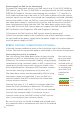
STEP 5: FURTHER CONNECTIONS (OPTIONAL)
If desired, connect additional wires to the installation site of the video door
station. The wires or connection options mentioned in this section are optional.
Be sure to use
four insulated,
shielded and
twisted wires of
a network cable
in accordance
with the Cat.5
standard or
better.
Connecting the unit to a network
You can connect the video door station to your existing
network via WiFi, or alternatively use a network cable
(Ethernet). For reasons of network stability, we principally
recommend using a network cable, as WiFi is sensitive to
interference (range, house walls acting as shields, relia-
bility of performance, third party WiFi networks, wireless
transmitters causing interference in the area, etc.).
The video door station can be powered by PoE or using
the power supply unit provided. If you use PoE as a
source of power, the WiFi interface of the video door
station remains inactive.
Use only four wires (1, 2, 3 and 6) of a network cable that
meets the Cat.5 standard or a better one. The other four
wires of the network cable (4, 5, 7 and 8) are not required.
Connect the network cable in the house to your
Internet router or to your PoE switch or PoE injector
that is connected to your Internet router.
Be sure to use four insulated, shielded and twisted wires
of a network cable in accordance with the Cat.5 standard
or better.
6 (R-)
3 (R+)
2 (T-)
1 (T+)
Power supply via PoE (as an alternative)
To power the video door station via a PoE switch (e.g. D-Link DGS-1008P) or
PoE injector (e.g. TP-Link TL-PoE150S) in accordance with the PoE standard
IEEE 802.3af Mode A, the four wires bearing the numbers 1, 2, 3 and 6 of a
Cat.5 cable or better are to be used. A Cat.5 cable or better must be used as
network signals can only be transmitted over completely insulated, shielded
and twisted cables. If you use PoE as a source of power, the WiFi interface of
the video door station is automatically inactive, and the four wires for PoE
then simultaneously form the data link. The video door station won’t start
if your PoE Switch or PoE injector does not support the PoE Standard IEEE
802.3af Mode A (see Diagnostic-LED and Diagnostic-Sounds).
1. Disconnect the PoE switch or PoE injector from the power grid.
2. Place the network cable in the installation site of the video door station.
Do not combine the power supply from the power supply unit (mains adaptor)
with the power supply via PoE.