Owner’s Manual Model 1808 and 1810 Access Plus Systems PC Programmable Telephone Entry / Access Control System DoorKing, Inc. 120 Glasgow Avenue Inglewood, California 90301 U.S.A. Phone: 310-645-0023 Fax: 310-641-1586 www.doorking.com P/N 1810-162 REV J, 1/12 Copyright 2009 DoorKing, Inc. All rights reserved.
Page 2 1810-162-J-1-12
Use this manual with the following models only. 1808 and 1810 Access Plus Telephone Entry / Access Control Systems with circuit board 1970010. DoorKing, Inc. reserves the right to make changes in the products described in this manual without notice and without obligation of DoorKing, Inc. to notify any persons of any such revisions or changes. Additionally, DoorKing, Inc. makes no representations or warranties with respect to this manual. This manual is copyrighted, all rights reserved.
Table of Contents Preface Important Notices......................................................................................................................................................6 General Information ..................................................................................................................................................7 Features ............................................................................................................................................
2.5 Directory Codes 2.5.1 2.6 2.7 Directory Codes 24 – 50 Dial Phone Number ..........................................................................43 2.5.3 Delete Phone Number from Directory Codes 24 - 50 ..............................................................43 2.5.4 Delete All Phone Numbers from Directory Codes 24 - 50........................................................43 Devices 2.6.1 Simple Access Code Programming ..................................................................
Important Notices FCC – United States This equipment has been tested and found to comply with the limits for a class A digital device, pursuant to Part 15 of the FCC Rules and Regulations. These limits are designed to provide reasonable protection against harmful interference when the equipment is operated in a commercial environment.
General Information Prior to beginning the installation of the telephone entry system, we suggest that you become familiar with the instructions, illustrations, and wiring guidelines in this manual. This will help insure that you installation is performed in an efficient and professional manner. The proper installation of the telephone entry panel is an extremely important and integral part of the overall access control system.
Features IP Addressable – program from your PC using the DoorKing programming software via a LAN or WAN connection, or via a built-in modem. When internet connection is provided, system can send e-mail notification on 58 selectable events and 20 access codes. Two internal relays allow the system to control a main entry gate plus a pedestrian access gate. Control up to six (6) additional entry points with card readers, keypads or wireless RF via RS485 connection.
SECTION 1 - INSTALLATION Installation of the Access Plus Telephone Entry and Access Control System involves the installation of the hardware and the wiring of these components. If used to control a vehicular gate with an automatic gate operator, the telephone entry system must be mounted a minimum of six (6) feet away from the gate and gate operator, or in such a way that a person cannot operate the entry system and/or touch the gate or gate operator at the same time. 1.
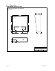
1.2 Dimensions Surface Mount 1810 Access Plus Standard Surface Mount Housing Case and Mounting Hole Dimensions 4.75 10.125 13.0 10.875 .25 DIA 9.0 .875 DIA 1 8.75 2.625 3.25 11.25 1.625 2.625 .875 DIA DOORKING, INC., INGLEWOOD, CA 90301 Title: Date: Page 10 Surface Mount Case and Mounting Hole Dimensions 10/09 Dwg. No. M1810-AP-1 Rev.
Surface Mount 1810 Access Plus with Recess Box/Trim Ring Standard Surface Mount Recess Mounting Box (P/N 1803-150) 13.375 3.625 1.625 10.125 2.25 3.375 2.187 .437 4.875 10-24 x 1.25 STUD (4 PL) .25 DIA 13.25 15.25 8.5 10.875 11.0 8.375 9.0 9.0 .25 DIA 2.187 1.375 DIA 3.687 1.125 6.0 6.0 3.5 2.187 Recess Mount Box .25 DIA 3.5 .437 Surface Mount Entry System 2.063 2.687 11.375 DOORKING, INC.
Flush Mount 1810 Access Plus 1.125 Flush Mount Units 12.0 10.125 1.125 3.0 13.0 13.25 10.875 .25 DIA 2.625 .50 .875 9.0 .875 DIA 2.625 5.625 1.625 11.25 .875 DIA 2.5 DOORKING, INC., INGLEWOOD, CA 90301 Title: Date: Page 12 Flush Mount Units 10/05 Dwg. No. M1800-065-3 Rev.
Flush Mount Rough-in Box (1810 Access Plus only) Flush Mount Rough-in Box 1.300 (Flush mount rough-in box is included with the 1814-165 and 1814-166 flush mount kits) 3.450 1.914 12.800 3.000 10.120 3.000 3.000 .275 DIA (5 PL) 1.500 1.800 1.125 DIA (3 PL) 3.000 .275 DIA (3 PL) 3.000 6.000 3.400 1.740 3.400 1.800 1.685 14.600 10.886 3.000 10-32 x .75 Stud (4 PL) 1.740 1.125 DIA (2 PL) 4.700 4.700 1.700 DOORKING, INC.
Flush Mount Trim Ring (1810 Access Plus only) Flush Mount Trim Ring (P/N 1814-165 and 1814-166) 14.700 3.450 10.120 .286 DIA (4 PL) 13.555 16.055 10.886 1.250 1.250 DIA (3 PL) 4.505 3.100 Trim Ring Entry System 3.100 Rough-in Box 1.575 1.250 DIA (3 PL) 3.000 1.325 3.000 12.200 DOORKING, INC., INGLEWOOD, CA 90301 Title: Date: Page 14 Flush Mount Trim Ring 4/11 Dwg. No. M1800-065-5 Rev.
Surface Mount Trim Ring for Flush Mount Units (1810 Access Plus only) Surface Mounting Kit for Flush Style Units (P/N 1814-152) 12.0 1.0 2.625 13.5 .375 1.125 DIA Flush Mount Ring 3.0 1.125 SQ Flush Unit 6.0 1.125 .375 7.5 .875 9.0 DOORKING, INC., INGLEWOOD, CA 90301 Title: Date: 1810-162-J-1-12 Surface Mount Kit for Flush Style Units 11/09 Dwg. No. M1800-065-6 Rev.
Surface Mount 1808 Access Plus 1808 Surface Mount Housing 6.375 3.50 7.375 3.50 .875 3.375 3.0 2.625 .875 DOORKING, INC., INGLEWOOD, CA 90301 Title: Date: Page 16 1808 Surface Mount Case 9/03 Dwg. No. M1800-065-10 Rev.
Postal Switch Installation (1810 Access Plus only) The 1808 Access Plus unit does not have provisions for the installation of the postal switch. If letter carrier access is required when using the 1808, the postal switch can be mounted in the DoorKing P/N 1402-080 - Postal Lock Box. Postal Lock Installation Detail Common to Terminal 9 1 2 Normally Closed to Terminal 7 or 8 3 4 1 Connect to terminal 7 to activate relay 1; connect to terminal 8 to activate relay 2. 2 Micro-switch is pre-wired.
Page 18 1810-162-J-1-12
1.3 Power Wiring Do not run telephone lines / data lines and high voltage lines in the same conduit. Separate high voltage and telephone / data line conduits by at least six (6) inches. POWER WIRING WIRE SIZE MAX DISTANCE IN FEET 18 AWG 100 16 AWG 200 Access Plus Units operate on 16.5 VAC. Do not power these devices with 24 volt AC power. If the OV LED is ON, the input voltage is too high. Check the transformer to be sure it is rated at 16 VAC.
Telephone Auto-Dialer Wiring – Single Unit A White/Blue 1 Blue/White Ring Tip Gnd Gnd White/Orange Ring Tip 2 Orange/White Vehicular Gate Operator 1 4 3 5 4 5 White/Blue Blue/White Blue/White White/Blue 7 6 8 7 6 9 RS-485 RX ON SW2 BAD DNS LAN DOWN ON SW1 MODEM / TCP ENB Phone Line In Use 8 10 1 Master Code TERMINATION 2 OFF 6 6 1 2 3 Data Transmit From Phone Company LAN Connection 1.4 11 Mic Vol 12 13 Keypad 14 15 16 Mag Lock Power 3 4 16.
Telephone Auto-Dialer Wiring – Multiple Units B White/Blue 1 Blue/White Ring Tip Gnd Gnd White/Orange Ring Tip 2 Orange/White Vehicular Gate Operator 2 1 2 OFF 4 3 5 4 5 White/Blue Blue/White 6 Blue/White White/Blue 7 6 8 7 9 6 11 RS-485 RX ON SW2 BAD DNS LAN DOWN ON SW1 MODEM / TCP ENB Phone Line In Use 8 1st Unit 10 6 Master Code TERMINATION 3 Data Transmit From Phone Company LAN Connection 1.
1.6 Telephone Intercom Wiring From Phone Company Relay 01 Thru A 4 Relay 11 RJ71C Block 1 RJ71C Block 2 3 3 Relay 12 Note: Relay 00 is reserved for Central Office (C.O.) phone line for Access Plus Auto-dialer and modem programming. Directory codes 01 to 23 are reserved for use with the 1816 Access Plus Cabinet. Program these directory codes if using this option. Only a single (1) Access Plus system can be used when interfacing with the 1816 Access Plus cabinet.
1.7 1816 Access Plus Detail Wiring 2 1881 Decoder Board 1 2 Phone Line Wire Size 1 3 4 5 6 7 8 9 10 Wire Size Max Distance (Ft) 24 AWG 800 22 AWG 1600 1 1 1 1 1 2 3 4 4 5 7 8 8 9 11 MODEM / TCP ENB 6 7 10 ON SW1 5 6 3 Master Code 2 3 Access Plus System 12 Mic Vol Keypad 13 14 15 16 17 18 Speaker Vol 1 1 Use only twisted pair telephone wire that is rated for direct underground burial. DO NOT use wire that is intended for indoor applications .
Page 24 1810-162-J-1-12
1.8 Main Terminal Description Terminal Description 1 Phone In (Negative) 2 Phone In (Positive) 3 Ground 4 Phone Out (Positive) 5 Phone Out (Negative) 6 Not Used. 7 Switch Input Relay 1. A switch closure across terminals 7 & 9 will activate relay 1 for its programmed strike time. 8 Switch Input Relay 2. A switch closure across terminals 8 & 9 will activate relay 2 for its programmed strike time. 9 - 12 VDC Battery Negative. Also common for terminals 7 & 8. 10 + 12 VDC Battery Positive.
1.9 Access Plus Interface Board The Access Plus interface board is piggybacked onto the main Access Plus circuit board. The interface board provides additional connections to the Access Plus unit for card readers, keypads and/or RF receivers using RS-485 communication protocol. It also provides connections to the 1816 Access Plus decoder board when the system is used in the telephone intercom mode. Access Plus units can be programmed via a PC using a network or modem connection.
RS-485 Connections RS-485 Terminal Connections Access Plus Board 4 1 TERMINATION 1 2 OFF RS-485 RX ON SW2 3 7 BAD DNS LAN DOWN 4 Term 7 RS-485 Data B ( - ) Term 3 RS-485 Common Phone Line In Use Term 6 RS-485 Common Terminal 1 from the Access Plus board connects to RS-485 board(s) terminal 8. Terminal 2 from the Access Plus board connects to RS-485 board(s) terminal 7. Terminal 3 from the Access Plus board connects to RS-485 board(s) terminal 6.
1.9.2 Network Connections There are a number of ways to communicate with the Access Plus unit via a network connection. Before any programming can be attempted, you need to install the Access Plus Account Manager programming software on the computer you want to use for this purpose. The computer must have a network card installed. Follow the instructions in the software help guide and refer to section 2.3 for setup information.
Direct Connection Using a Crossover Cable 1 Master Code TERMINATION 2 OFF ON RS-485 RX SW2 4 3 5 4 6 5 7 6 8 9 7 BAD DNS LAN DOWN ON Data Transmit 2 3 LAN Connection 1 SW1 MODEM / TCP ENB Phone Line In Use 8 10 11 Mic Vol 12 1 13 Crossover Cable Keypad 14 15 16 17 18 1 325 Feet (100 Meters) maximum. Speaker Vol 1 2 3 4 5 6 7 8 9 1011 Direct Connection Using a Router (LAN) Modem N.I.D.
Through the Internet (WAN) 2 4 3 5 4 6 7 5 8 7 9 10 8 Router 1 2 3 4 Master Code TERMINATION 2 OFF ON RS-485 RX SW2 6 BAD DNS LAN DOWN ON LAN Connection Modem N.I.D. 1 3 Data Transmit 1 SW1 MODEM / TCP ENB Phone Line In Use 11 Mic Vol 12 13 Keypad 14 15 DSL / Cable Modem 16 17 18 LAN Speaker Vol INPUT 1 2 3 4 5 6 7 8 9 1011 Phone / Cable Company Input 1 Internet Wired or Wireless 1 Page 30 325 Feet (100 Meters) maximum.
1.9.3 Modem Connections Access Plus unit’s have a built-in modem that can be used to connect to a PC. Before programming can be attempted, you need to install the Access Plus Account Manager programming software on the computer you want to use for this purpose. The computer must have a modem installed or an external modem connected to it. Follow the instructions in the software help guide for setup information.
SECTION 2 – PROGRAMMING Before You Start IMPORTANT! We strongly suggest that you become familiar with these programming instructions before beginning any programming of the Access Plus unit. The Access Plus unit has been programmed at the factory with many of the programming parameters already set (default setting) for a typical application with a single Access Plus unit. There is no need to reprogram these parameters unless you want to change them.
2.2 Programming Methods Access Plus units can be programmed from a computer, the unit’s keypad or from a touch-tone telephone connected to the unit. We highly recommend programming the Access Plus unit from a computer using the Access Plus Account Manager software as this greatly simplifies the programming task. There are also several features in the Access Plus unit that must be setup using a computer. The following features and programming parameters can only be programmed from a computer.
2.3 Programming with a Computer (Network Setup) Before proceeding with any of the programming steps in this section, install the Access Plus Account Manager software on the computer that will be used for this purpose. Be sure that the computer has a network card installed, or a modem installed in it (or connected to it) depending on which connection method will be used.
2.3.3 Sub-Net Mask (reboot required) Default value is: 255.255.255.000 All sub-net mask should be set to 255.255.255.000. If not, consult your network expert. Valid values for any of the three digit numbers is 000 to 255. 1. Press * 5 2 and enter the MASTER CODE. [* 5 2 _ _ _ _ (beep)] 2. Enter the sub-net mask number. Use the * key to enter the “dot.” [ _ _ _ * (beep) _ _ _ * (beep) _ _ _ * (beep) _ _ _ * (beep)] 3. Press 0 # TOGETHER to end. [0 # (beeeeeep)] 2.3.
2.4 System Parameters Programming IMPORTANT! We strongly suggest that you read these programming instructions in their entirety before beginning any manual programming of the Access Plus unit. The programming table on the next page provides a quick reference to the Programming from the Keypad Follow the programming instructions as described in each section of this manual.
System Parameters Programming Section 2.4 Description Command Section Default Value Single / Multiple Units *61 2.4.1 Single Single or Double Ring (1816 Access Plus only) *63 2.4.2 Double Number of Rings to Resident (1816 Access Plus only) *64 2.4.3 5 Talk Time *08 2.4.4 60 Sec. Relay Strike Time *03 2.4.5 Tone Open Numbers *05 2.4.6 Answer Incoming Call on X Rings *18 2.4.7 1 Sec Relay 1: 9 8 7 6 Relay 2: 5 4 3 2 6 Hang-up Tone *17 2.4.
2.4.1 Single or Multiple Units Default setting is 1 (Single Unit). Set for single if only one Access Plus unit is connected to the phone line, or set to multiple if more than one Access Plus units are connected to the phone line. 1. Press * 6 1 and then enter the MASTER CODE. [ * 6 1 _ _ _ _ (beep)] 2. Press 1 * for a single system OR press 0 * for multiple systems. [ _ * (beep)] 3. Press 0# TOGETHER to end. [0# (beeeeeep)] 2.4.2 Single or Double Ring Default setting is 1 (Double Ring).
2.4.3 Number of Rings to Ring Residence Default setting is 05 (5 Rings). This programming step is only used if the Access Plus unit is connected with the 1816 Access Plus interface. This programming step is not applicable when the Access Plus unit is used as an auto-dialer. This programming sequence sets the number of unanswered rings to the apartment before the Access Plus unit hangs up. 1. Press * 6 4 and then enter the MASTER CODE. [ * 6 4 _ _ _ _ (beep)] 2.
2.4.6 Tone Open Numbers Default setting is 9876 for relay 1; 5432 for relay 2. Relays 3 – 8 are not set. These steps will program the tone open number(s) for each relay in the system (each relay is programmed independently). You will need to enter a four-digit number (see chart below) to set each relay. If a function is not desired, enter # in place of a number.
2.4.8 Hang Up Tone Default setting is 0. These steps set the number that will hang-up the Access Plus unit after conversation is completed. 1. Press * 1 7 and enter the MASTER CODE. [ * 1 7 _ _ _ _ (beep)] 2. Enter the hang up tone number then press *. [ _ * (beep)] 3. Press 0# TOGETHER to end. [0# (beeeeeep)] 2.4.9 Call Waiting Default setting is 1 (Call Waiting On). This programming step is only used if the Access Plus unit is connected with the 1816 Access Plus interface.
2.4.11 Set Microphone Gain and Speaker Volume Default setting is 71. This adjustment is required only if the Access Plus unit is being used in the auto-dialer mode (directory codes 24-50). This step will adjust the microphone gain (the remote handset loudness) and the speaker volume (the Access Plus unit loudness) during call forwarding operation. You may have to perform these steps several times to get the optimal microphone gain and speaker volume adjustment.
2.5 Directory Codes 2.5.1 Directory Codes 01 – 23 1816 Intercom Relay Programming Default Value is 0 (Directory codes 01-23 are turned off) Directory codes 01-23 are pre-set to dial relay numbers and telephone intercom lines associated with the 1816 system. Use this programming step if the 1816 Access Plus module is attached to the 1808 or 1810 Access Plus System. 1. Press * 4 1 and enter the MASTER CODE. [* 4 1 _ _ _ _ (beep)] 2. Enter a two-digit directory code (01-23) then press *. [ _ _ (beep)] 3.
2.6 Access Devices NOTE: All access codes are five (5) digits in length. 2.6.1 Simple Access Code Programming This programming sequence programs simple access codes used on the Access Plus units keypad into the system memory. Simple access codes cannot be time zone restricted; they can only be assigned to operate either relay 1 or relay 2 on a 24/7 basis. If you require access codes to be time zone restricted, use the programming sequence in 2.6.4.
2.6.4 Device Access Code Programming This programming sequence programs device (card readers, keypads, RF receivers, etc.) access codes into the system memory with time zone restrictions applied. It also allows programming of the device access codes to momentarily activate a relay or to hold (latch) a relay. 1. 2. 3. 4. Press * 7 0 and enter the MASTER CODE. [ * 7 0 _ _ _ _ (beep)] Enter the device type (0=card, 1=transmitter, 2=keypad, 3=other), then press *.
2.6.7 Temporary Device Access Code Programming This programming sequence programs up to 10 temporary device access codes with a beginning and ending date and any time zone restrictions that may need to be applied. 1. 2. 3. 4. 5. 6. Press * 7 3 and enter the MASTER CODE. [ * 7 3 _ _ _ _ (beep)] Enter the device type (0=card, 1=transmitter, 2=keypad, 3=other), then press *. [ _ * (beep)] Enter a five-digit device access code then press *.
2.7 Time Functions 2.7.1 Program Calendar Chip This programming sequence programs the calendar chip in the Access Plus unit for the current time and date. The calendar chip must be programmed if any of the time related features are going to be used. Note: The clock / calendar chip in the Access Plus unit will keep time for approximately 48 hours if power to the system is lost or removed. If power is off longer than this, the clock / calendar chip will have to be reprogrammed. 1. 2. 3. 4.
2.7.2 Relay Hold Schedule Default setting in step 3 is 0 (Hold schedules are OFF). This program sequence sets up schedules to automatically activate and deactivate relays 1 through 8. Four schedules can be programmed, each of which can be assigned to the desired relay(s). These schedules can be independently turned on or off after they have been programmed. 1. Press * 3 5 and enter the MASTER CODE. [ * 3 5 _ _ _ _ (beep)] 2. Enter a schedule number (1, 2, 3 or 4) then press *. [ _ * (beep)] 3.
2.7.3 Time Zones Default setting in step 3 is 0 (Time Zones are OFF). This programming sequence sets up time zones (up to 4) that can be applied to the device access codes programmed into the Access Plus unit. These time zones can be turned on or off once they have been programmed. 1. Press * 3 6 and enter the MASTER CODE. [ * 3 6 _ _ _ _ (beep)] 2. Enter a time zone number (3, 4, 5 or 6) then press *. [ _ * (beep)] Do not use 0, 1 or 2 for time zone numbers.
2.8 Miscellaneous 2.8.1 Restore Defaults This step will restore the factory set defaults for each of the programming parameters. WARNING: Once started, this sequence will program all values to factory default. 1. Press * 9 0 and enter the MASTER CODE. [ * 9 0 _ _ _ _ (beep)] 2. Press 9 9 9 9 then press *. [ 9 9 9 9 * (beep)] 3. This sequence will end itself automatically. [beeeeeep] 2.8.
SECTION 3 – ADJUSTMENTS Speaker Volume The speaker volume potentiometer is labeled SPEAKER VOL on the control board. The speaker volume should be adjusted for adequate sound. Adjusting the speaker volume too loud could cause feedback from the microphone. 1. Open the front of the telephone entry system and locate the speaker volume adjustment. 2. Place a call to a resident by entering a directory code on the keypad. While they are talking, adjust the speaker volume potentiometer for adequate sound.
Interface Board LED Status 1 TERMINATION 2 OFF RS-485 RX ON SW2 3 BAD DNS LAN DOWN 4 ON Data Transmit 6 LAN Connection SW1 5 MODEM / TCP ENB Phone Line In Use 7 8 RS-485 RX Green LED indicates that the system is on-line and scanning the RS-485 devices. BAD DNS Yellow LED indicates an email server problem, rejecting the mail server. LAN DOWN Red LED indicates a problem with the LAN. IP or Gateway (router) down or wrong gateway IP address.
SECTION 4 – USER INSTRUCTIONS 4.1 Resident Operating Instructions 4.1.1 Granting or Denying a Guest Access To place a call from the Access Plus unit to a residence, the guest locates the directory code of the resident they want to visit, and then enters that code on the unit’s keypad.
4.1.3 Dial-Connect (1816 intercom) To use the dial-connect feature, the guest simply presses a two-digit directory code (01-23) on the Access Plus unit’s keypad. The unit will automatically connect to the resident phone programmed under the directory code that was entered on the keypad. Once the call is answered, the person called may grant access by pressing the programmed tone open number or they can press the hang up number (2.4.8) to disconnect the call without granting access. 4.1.
4.2 Remote Operation 4.2.1 Remote Programming The Access Plus unit can be programmed and operated from a remote location using a touch-tone telephone. Be sure that the ability for the unit to answer an incoming call has not been disabled (see 2.4.7). Note: The Access Plus unit master code cannot be programmed remotely – it can only be programmed from the system keypad – see Programming the Master Code on page 32. 1. Call the unit’s phone number. After the programmed number of rings (2.4.
4.2.3 Relay Activation Check The Access Plus unit can be called to check if relay 1, relay 2, or both relays on the unit’s main circuit board are latched and holding a door or gate in the open (unlocked) position. 1. Call the phone number that the Access Plus unit is connected to. After the programmed number of rings (2.4.7) the unit will answer with a tone. 2. Press * 1 6 and enter the MASTER CODE. [ * 1 6 _ _ _ _ (beep)] 3. Press * 7. [ * 7 (beep)] 4. Listen for the following sequence of tones.
SECTION 5 – MAINTENANCE The DoorKing Access Plus system is essentially a maintenance free device. When the unit is properly installed, it should provide years of trouble free service. Maintenance is limited to updating the access codes and temporary access codes on an as needed basis. The faceplate of the unit should be cleaned on a regular basis to keep contaminants in the air from sticking to the surface and possibly causing pitting.
5.2 Troubleshooting Tables SYMPTOM POSSIBLE SOLUTION(S) Board does not power up. No power. Check for 16 VAC input power. If OV LED is ON, input voltage is too high. connected to the input terminals is 16 VAC. Cannot get into programming mode. Wrong master code entered. Start over. Waiting too long between pushing buttons. Enter information quicker. Keypad is not plugged into board correctly. Cable points down. System emits a long tone and cancels programming.
5.3 Wire Diagram 1 1 2 2OFF 3 3 4 4 5 5 6 6 7 7 8 8 TERMINATION Master Code ON SW2 ON SW 1 MODEM / TCP ENB 9 10 11 Mic Vol Keypad 12 13 14 15 16 17 18 Speaker Vol 1 2 3 4 5 6 7 8 9 1011 7 8 9 10 11 Gray 6 Orange 5 White 4 Purple 3 Green Red 2 White 1 1 N.C. Micro Switch Red LED PCB COM White Microphone PCB N.O. LED PCB + - LED PCB 2 1 Postal micro-switch is used in 1810 Access Plus units only.
5.
5.5 Tables Complete the information in the tables on the following pages to maintain a record of the information that has been programmed into the 1810 entry system. MASTER CODE Tone Number Function Relay 1 2 3 4 5 6 7 8 Momentary Hold Release Hold 1 Hr.
Directory Codes / Dial-Connect Directory Code Name Apartment Number 02 03 04 05 06 07 08 09 10 11 12 13 14 15 16 17 18 19 20 21 22 23 Page 62 1810-162-J-1-12
Directory Codes / Auto-Dial Numbers Directory Code Name Phone Number 24 25 26 27 28 29 30 31 32 33 34 35 36 37 38 39 40 41 42 43 44 45 46 47 48 49 50 1810-162-J-1-12 Page 63
Access Code Log Sheet Name Page 64 Device Access Code Device Type Time Zone Schedule Number Relay Momentary or Hold 1810-162-J-1-12
Name 1810-162-J-1-12 Device Access Code Device Type Time Zone Schedule Number Relay Momentary or Hold Page 65