
Manual
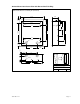


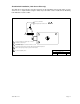

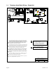

1.4 Telephone Auto-Dialer Wiring – Single Unit
DOORKING, INC., INGLEWOOD, CA 90301
Date: Dwg. No. Rev.
Title:
1/12
C
M1810-AP-6-C
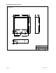
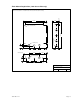
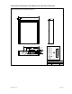
Access Plus System Auto-Dialer Wiring
Basic wire connections – single unit.
1
Magnetic locks or electric strikes must be powered from a separate UL Listed
power transformer. Do not power strikes or magnetic locks from the 1810 power
transformer.
3
1
2
2
A
Use supplied 16.5 VAC, 20 VA power transformer or UL Listed equivalent.
DO NOT Power this device with a 24 Volt transformer or source voltage.
Use only twisted pair telephone wire that is rated for direct underground burial.
DO NOT use wire that is intended for indoor applications. Recommend
Cat5e Gel Filled (flooded) UV Resistant Direct Burial Cable in conduit. DO
NOT run telephone wires and high voltage wires in the same conduit .
Check the phone wire chart for wire size / distance.
Check for polarity on the phone "IN" wires, terminals 1 and 2. Terminal 2 must be
positive with respect to terminal 1. Set a VOM meter to measure DC volts. Place
the positive lead on terminal 2 and the negative lead on terminal 1. If the meter
shows a positive voltage - OK. If the meter shows a negative voltage (needle
moves off scale to the left), reverse the wires on terminals 1 and 2.
4
5
6
Use minimum 18 AWG wire for runs up to 100 feet; 16 AWG wire for runs up to
200 feet. It is recommended to keep power wire runs as short as possible.
Check the power wire chart for wire size / distance.
Be sure to properly ground all devices. Minimum 12 AWG wire. Surge devices
must have a ground point within 3-ft of the device.
B
Optional DoorKing Surge Suppresser P/N 1877-010 (or
equivalent) highly recommended.
For best protection, surge suppresser ground wire must be
3-ft. or less in length. Use minimum 12 AWG wire.
Ring is Positive with respect to Tip terminal. See
6
This device is powered by a 16.5 VAC
transformer. DO NOT power this device with a
24 VAC transformer or power source.
Ring
Tip
Ring
Tip
Gnd
Gnd
From Phone
Company
Blue/White
Orange/White
White/Orange
White/Blue
Blue/White
White/Blue
3
16.5 VAC
20 VA
White/Blue
Blue/White
Vehicular Gate
Operator
Pedestrian
Gate / Door
Mag Lock
Power
4
A
5
B
1
6
1
2
3
4
5
6
7
8
9
10
11
12
13
14
15
16
17
18
Mic
Vol
Master
Code
1234567891011
Speaker
Vol
Keypad
ON
SW1 MODEM / TCP ENB
1
2
3
4
5
6
7
8
BAD DNS
RS-485 RX
LAN DOWN
Phone Line
In Use
LAN
Connection
Data
Transmit
SW2
ON
TERMINATION
OFF
Page 20 1810-162-J-1-12