
User Manual


1812-161-L-12-11
10
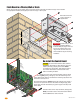
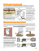
Mount rough-in box into the pilaster, wall or kiosk. Run conduit inside wall into bottom of rough-in box if desired.
Use appropriate hardware (Not supplied) to secure the rough-in box in place.
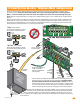
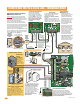
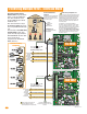
Remove the 18-pin main terminal connector from the control
board by gently pulling it straight up. This will make wiring to the
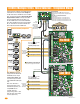
control board easier. Note the orientation and numbering sequence of the
connector to correctly wire it.
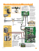
Re-install control board by carefully routing all incoming wires around it
and secure it in place with 4 screws. Re-connect the keypad plug (cable
points down) and door accessories plug (red wire goes to the left) to the
control board.
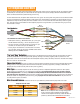
Connect all wires to the 18-pin connector (See page 18).
Gently re-connect it back on the control board. DO NOT
APPLY POWER to the 1812 at this time.
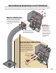
Bolt flush box into the
rough-in box with 4
supplied bolts.
Flush Mount in a Pilaster, Wall or Kiosk
Re-install the Control Board
Rough-In Box
SP
E
A
K
E
R
V
OL
MIC
V
OL
K
E
Y
PAD
MA
S
T
E
R
C
ODE
1970-
0
10
18
1
1
1234
56
7
8910
17
16
15
14
13
12
11
10
9
8
7
6
5
4
3
2
1
J
2
J1
J
3
J
3
J
CAUTION The control board contains static sensitive
components. Discharge any static electricity from your
hands by touching a proper ground device before
re-installing the control board. Also make sure that all
dirt, metal or wood debris is removed from inside
before re-installing the board.
IMPORTANT Choose how your 1812
will function (Telephone Mode or
Intercom Mode) on pages 14 thru 18
and run the indicated wires to the
rough-in box. Run ALL wires that
will be needed during the mounting
installation.
Keypad
Plug
18-Pin
Main
Terminal
Connector
Door
Accessories
Plug
Conduit
in Wall
1972-011
Flush
Box
7
7
8 9
4 5 6
0
10.25”
7.5”
4.5”