Owner’s Manual 1819 Information Phone DoorKing, Inc. 120 Glasgow Avenue Inglewood, California 90301 U.S.A. Phone: 310-645-0023 Fax: 310-641-1586 www.doorking.com P/N 1819-065 REV B, 4/07 Copyright 2007 DoorKing, Inc. All rights reserved.
1819-065-B-4-07 Page 2
1819-065-B-4-07 Use this manual with the following models only. 1819 Information Telephone with circuit board 1862-010, Rev I or higher. DoorKing, Inc. reserves the right to make changes in the products described in this manual without notice and without obligation of DoorKing, Inc. to notify any persons of any such revisions or changes. Additionally, DoorKing, Inc. makes no representations or warranties with respect to this manual. This manual is copyrighted, all rights reserved.
1819-065-B-4-07 Page 4
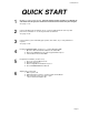
1819-065-B-4-07 QUICK START 1 Mount the Telephone Entry System. If the unit is being used to provide access through an automated vehicular gate, the unit must be mounted at least 10-feet away from the gate. See pages 11-13. 2 Connect 16 VAC power to terminals 13-14. Connect a dedicated touch-tone loop-start phone line to terminals 1-2. Connect ground wire to terminal 3. See pages 15-18. 3 Connect device(s) to be activated (gate operator, door strikes, etc.) to relay terminals as required.
1819-065-B-4-07 TABLE OF CONTENTS Preface Important Notices......................................................................................................................................................8 Important Information................................................................................................................................................9 Features ............................................................................................................................
1819-065-B-4-07 Section 4 – Operating Instructions 4.1 4.2 4.3 General Instructions 4.1.1 Calling Instructions ...................................................................................................................29 4.1.2 Responding to a Call ................................................................................................................29 System Administrator 4.2.1 Remote Programming ......................................................................................
1819-065-B-4-07 IMPORTANT NOTICE FCC - UNITED STATES This equipment has been tested and found to comply with the limits for a class A digital device, pursuant to Part 15 of the FCC Rules and Regulations. These limits are designed to provide reasonable protection against harmful interference when the equipment is operated in a commercial environment.
1819-065-B-4-07 IMPORTANT INFORMATION • Prior to beginning the installation of the information telephone, we suggest that you become familiar with the instructions, illustrations, and wiring guidelines in this manual. This will help insure that you installation is performed in an efficient and professional manner. • The proper installation of the information telephone is an extremely important. Check all local building ordinances and building codes prior to installing this system.
1819-065-B-4-07 Page 10
1819-065-B-4-07 SECTION 1 - INSTALLATION Order your telephone line at least two weeks prior to the planned installation date. This will assure that a phone line is available when the unit is installed. The telephone company will require the following information from you: Type: Ringer Equivalence: Jack Type: FCC Registration (US): DOC (Canada): 1.1 Touch Tone, Loop Start 0.0 A RJ11C DUF6VT-12874-OT-T 1736 4528 A Installation Guidelines 1.
1819-065-B-4-07 1.2 Surface Mount Only Surface mount units can be mounted directly to a wall or pilaster, or can be post mounted using a DoorKing mounting post (p/n 1200-045 and 1200-046). Be sure the unit is mounted securely and is not subject to vibration from closing doors or gates.
1819-065-B-4-07 1.3 Memory Chip Installation The telephone entry system is shipped with a memory chip packaged in a separate box inside the shipping container. The memory chip must be installed for the telephone entry system to operate. CAUTION!! Do not install the memory chip with power to the telephone entry system turned on. Attempting to install the memory chip with power on will irrevocably damage the chip. CAUTION!! The memory chip is a static sensitive component.
1819-065-B-4-07 Page 14
1819-065-B-4-07 SECTION 2 – WIRING & ADJUSTMENTS Prior to installing wiring to the telephone entry system, we suggest that you become familiar with the instructions, illustrations, and wiring guidelines in this manual. This will help insure that you installation is performed in an efficient and professional manner. The wiring of the telephone entry panel is an extremely important. Use proper wire for the communication line, power wires, and be sure that the system is properly grounded.
1819-065-B-4-07 2.1 Circuit Board Adjustments 1862-010 Control Board Adjustments ON Master Code OFF CLICK SENS MIN MAX KEYPAD CONNECTOR 1 MIC VOLUME MIN MAX FEEDBACK 2 2 1 1 REV H Boards and later. 2 REV I Boards and later. 2 3 4 5 MAX MAX HANDSET TONE OFF MIN MIN 6 HANDS FREE TONE ON RING PIN SPEAKER VOLUME 7 8 9 10 11 12 13 14 DOORKING, INC., INGLEWOOD, CA 90301 Title: Date: Page 16 1819 Control Board Adjustments 4/07 Dwg. No. M1819-065-2 Rev.
1819-065-B-4-07 2.2 Wiring Diagram 1819 Field Wire Diagram - 1862-010 Control Board 1862-010 Circuit Board MAIN TERMINAL 1 2 3 4 5 6 7 8 9 10 11 12 13 14 Phone Line Wiring Max Distance 800 Feet 1600 Feet 24 AWG 22 AWG Power Wiring Max Distance Phone Line PWR INPUT 6 5 100 Feet 200 Feet 18 AWG 16 AWG 1 Earth Ground 4 1 16 Volt, 20 VA UL Listed power transformer. 2 Power for door strikes or magnetic lock is not provided by the system. It must be provided by an external power supply.
19-065-B-4-07 2.3 Terminal Description MAIN TERMINAL DESCRIPTION 1 Phone Line Connection – 800 ft. maximum with 24 AWG wire; 1600 ft. maximum with 22 AWG wire. 2 Phone Line Connection – 800 ft. maximum with 24 AWG wire; 1600 ft. maximum with 22 AWG wire. 3 Earth Ground Only – Not a Low Voltage Common! 4 Switch Input 1. A closure between terminals 4 and 8 will cause relay 1 to activate for the programmed strike time. The Postal Switch is connected here. 5 Microphone Input – White Wire.
1819-065-B-4-07 2.4 Adjustments 2.4.1 Speaker Volume 1. Open the front of the telephone entry system and locate the speaker volume adjustment. 2. Place a phone call from the telephone entry system. While the called person is talking, adjust the speaker volume potentiometer for adequate sound. To increase the volume rotate the potentiometer clockwise, to decrease the volume rotate the potentiometer counter clockwise. See Feedback adjustment (2.4.3 step 5). 2.4.2 Microphone Volume 1.
1819-065-B-4-07 2.4.5 Master Code Switch The master code switch is left in the off position for normal operation. Turn the master code switch on when setting the system master code. See programming instructions to set the system master code. If the master code switch is turned on and a new master code is not entered, the system will sound a long tone after approximately 30 seconds. This tone will continue every 30 seconds until a new master code is entered, or until the switch is turned off.
1819-065-B-4-07 SECTION 3 – PROGRAMMING The DoorKing 1819 Information Phone is programmed using the 1818-030 keypad assembly or remotely from an off premise location using a touch tone telephone. When programming from an off site location with a touch-tone telephone, the RING pin must be installed on the circuit board (see 2.4.6). We recommend that you do not attempt programming from an off site location until you become familiar with these programming instructions. Programming with the Keypad 1.
1819-065-B-4-07 3.1 General Programming 3.1.1 Master Code This programming step sets the system MASTER CODE. The master code is the four-digit number required to gain access to the system memory. You need to know the master code prior to performing any of the programming functions on the following pages. NOTE: The master code cannot be programmed from an off-site location. The master code can only be programmed from the system keypad. Factory setting = 9999 1.
1819-065-B-4-07 3.1.4 Tone Open Numbers These steps will program the tone open numbers for relay 1. You will need to enter a four-digit number (see chart below) to set the relay functions. If a function is not desired, enter # in place of a number. For example, if you want the relay to have a momentary activation function only, and you want the relay to activate when the number 9 is pressed, enter 9 # # # in step 3. Do not duplicate tone open numbers. Factory setting is 9876. 1. 2. 3. 4.
1819-065-B-4-07 3.1.7 System to Stay On-Line or Hang Up after Touch Tone This programming sequence provides a method for the telephone entry system to remain on line after a resident has pressed the touch tone number to open the door or gate. Factory setting = 1 (hang up after touch tone). 1. 2. 3. 4. Press *28 and enter the four-digit MASTER CODE _ _ _ _ (beep). Press 1* (beep). Press 0* (beep) to keep the system on line, or press 1* (beep) to make it hang up.
1819-065-B-4-07 3.2 Phone Number programming 3.2.1 Programming 7-digit Phone Numbers In this programming sequence, the directory code and 7-digit phone number will be programmed into the system. To program phone numbers that will be referenced to an area code (long distance calls and 10 digit calling), follow the instructions under Long Distance Phone Number Programming. NOTE: If this telephone entry system is being used in an area that requires 10-digit dialing, proceed to 3.2.2 and 3.2.
1819-065-B-4-07 3.2.4 Deleting Individual Phone Numbers This programming sequence is used to delete a single phone number. 1. 2. 3. 4. Page 26 Press *01 and enter the four-digit MASTER CODE _ _ _ _ (beep). Enter 001 then press * (beep). Press # # # # # # # then press * (beep). Press 0# TOGETHER to end this programming step (beeeeeep).
1819-065-B-4-07 3.3 Time Functions Programming 3.3.1 Time Clock Programming This programming sequence programs the calendar chip in the telephone entry system for the current time and date. The calendar chip must be programmed if you are going to use any of the time functions available with the entry system. 1. 2. 3. 4. 5. 6. 7. Press *33 and enter the four-digit MASTER CODE _ _ _ _ (beep). Enter the current hour and minutes _ _ _ _ then press * (beep).
1819-065-B-4-07 Page 28
1819-065-B-4-07 SECTION 4 – OPERATING INSTRUCTIONS Never allow children to operate or play with any access control device. 4.1 General Instructions 4.1.1 Calling Instructions When the CALL button is pressed, the system will call the preprogrammed telephone number. If the line is busy, the system will emit a busy signal. Pressing the CALL button will hang the system up. 4.1.
1819-065-B-4-07 4.2 System Administrator The administrator can perform the following operations from a remote location using a touch-tone telephone. You must know the phone number of the system and the system master code. 4.2.1 Remote Programming 1. Call the telephone number that the entry system is installed on. The system will answer with a short tone (beep). Note: the number of rings before the system answers is dependent on the programming in 3.1.6. 2.
1819-065-B-4-07 4.2.4 Auto Relay Time Zone Enable / Disable The two time zones that automatically activate and deactivate the relay can be turned off or on from a touch-tone telephone at any time without changing the time zone boundaries. To program the auto relay activation time zone boundaries, see section 3.3.2. 1. Call the telephone number that the entry system is installed on. The system will answer with a short tone (beep).
1819-065-B-4-07 4.3 Miscellaneous Operating Instructions 4.3.1 Line Sharing More than one telephone entry system can share the same phone line provided that the units have been programmed for multiple systems on the same line (see 3.1.2). When the unit is programmed for multiple systems sharing the same line, it checks the phone line for 48 volts (not busy) before attempting to place a call. If the phone line is in use, the system will emit a busy signal.
1819-065-B-4-07 SECTION 5 – MAINTENANCE The DoorKing telephone entry system is essentially a maintenance free device. When the unit is properly installed, it should provide years of trouble free service. Maintenance is limited to updating the directory and phone number and/or entry codes when residents move in or out. The faceplate of the unit should be cleaned on a regular basis to keep contaminants in the air from sticking to the surface and possibly causing pitting.
1819-065-B-4-07 SYMPTON Cannot get into programming mode. POSSIBLE SOLUTION(S) • Wrong master code entered. Start over. • Waiting too long between pushing buttons. Enter information quicker. • Keypad is not plugged into board correctly. Cable points down. • Memory chips are installed upside down. System emits a long tone and cancels programming. • Waiting too long between pushing buttons. • Forgetting to press * first when programming.
1819-065-B-4-07 5.3 Accessories Surge Suppressers Mounting Post Telephone Test Set Battery High voltage (120 V) suppresser: P/N 1878-076. Phone line suppresser: P/N 1878-077. Low voltage (28 V) suppresser: P/N 1878-078. Standard gooseneck mounting post: P/N 1200-045. Standard gooseneck mounting post – long: P/N 1200-046 Includes clips, cord and carrying case. P/N 1800-050. 12 volt .8 amp hour gel cell provides stand by power during power interruptions. P/N 1801-008.
1819-065-B-4-07 5.4 Log Tables Complete the information in the tables on the following pages to maintain a record of the information that has been programmed into the telephone entry system if the system. Make copies of the resident log sheet so that you have enough to complete a listing of all residents and data.
1819-065-B-4-07 Page 37