Owner’s Manual Model 1838 Access Plus PC Programmable Access Control System DoorKing, Inc. 120 Glasgow Avenue Inglewood, California 90301 U.S.A. Phone: 310-645-0023 Fax: 310-641-1586 www.doorking.com P/N 1838-066 REV D, 1/12 Copyright 2009 DoorKing, Inc. All rights reserved.
Page 2 1838-066-D-1-12
Use this manual with the following models only. 1838 Access Plus Access Control System with circuit board 1970-010. DoorKing, Inc. reserves the right to make changes in the products described in this manual without notice and without obligation of DoorKing, Inc. to notify any persons of any such revisions or changes. Additionally, DoorKing, Inc. makes no representations or warranties with respect to this manual. This manual is copyrighted, all rights reserved.
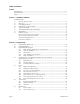
Table of Contents Preface Important Notices......................................................................................................................................................6 General Information ..................................................................................................................................................7 Features ............................................................................................................................................
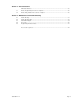
Section 3 – User Instructions LED Status Indicators...............................................................................................................................35 3.1 Remote Programming via Touch-tone Telephone ...................................................................................36 3.2 Remote Relay Activation via Touch-tone Telephone ...............................................................................36 Section 4 – Maintenance and Trouble Shooting 4.
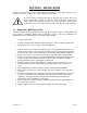
Important Notices FCC – United States This equipment has been tested and found to comply with the limits for a class A digital device, pursuant to Part 15 of the FCC Rules and Regulations. These limits are designed to provide reasonable protection against harmful interference when the equipment is operated in a commercial environment.
General Information Prior to beginning the installation of the access control system, we suggest that you become familiar with the instructions, illustrations, and wiring guidelines in this manual. This will help insure that you installation is performed in an efficient and professional manner. The proper installation of the 1838 Access Plus is an extremely important and integral part of the overall access control system.
Features The 1838 is an access controller that can control up to six (6) entry points via card, keypad or RF devices using RS-485 communication protocol. In addition, two (2) additional auxiliary relays are built into the system and are time zone controlled. These relays can be utilized to unlock or open a door or gate at preprogrammed times. IP Addressable – the 1838 Access Plus can be programmed from your PC using the DoorKing programming software via a LAN or WAN connection.
SECTION 1 - INSTALLATION Installation of the 1838 Access Plus system involves the installation of the 1838 controller, access devices (card readers, keypads, etc.), and the wiring of these devices. If used to control a vehicular gate with an automatic gate operator, the access devices (card readers, keypads, etc.
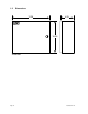
1.2 Dimensions 12.25 4.25 10.
1.3 Power Wiring POWER WIRING WIRE SIZE MAX DISTANCE IN FEET 18 AWG 100 16 AWG 200 The 1838 Access Plus operates on 16.5 VAC. Do not power this device with 24 volt AC power. If the OV LED is ON, the input voltage is too high. Check the transformer to be sure it is rated at 16 VAC. Use the supplied power transformer, 16 VAC, 20 VA (or U.L. listed equivalent) to power the access controller. Do not power any other devices (electric strikes, magnetic locks, etc.) from this power transformer.
1.5 Telephone Line Wiring (optional) This section is provided for information purposes if the 1838 Access Plus controller will be programmed via modem using a telephone line. Be sure to observe electrical safety when working with phone lines. Phone lines carry electricity and the ring voltage can deliver a substantial jolt. The best policy is to disconnect the phone line from the phone company Network Interface Device (also known as ‘Demarcation Device’) before working on the wiring.
Terminal Identification / Main Terminal Wiring 2 12 Volt Back-Up Battery Neg + 4 3 5 4 6 5 7 6 8 7 1838 Main Board Master Code TERMINATION 2 OFF 9 Pos 1 3 RS-485 RX ON SW2 BAD DNS LAN DOWN SW1 ON Data Transmit 1 LAN Connection 1.
1.7 RS-485 Wiring RS-485 Board RS-485 Terminal Connections 7 1 RS-485 Board TERMINATION 2 OFF RS-485 RX ON SW2 3 8 4 BAD DNS LAN DOWN 6 Data Transmit LAN Connection ON 5 SW1 Device Board Term 1 RS-485 Data A ( + ) Term 8 RS-485 Data A (+) Term 2 RS-485 Data B ( - ) Term 7 RS-485 Data B ( - ) MODEM / TCP ENB Term 3 RS-485 Common Phone Line In Use 7 Term 6 RS-485 Common Terminal 1 from the 1838 RS-485 board connects to Device board(s) terminal 8.
1.8 Network Connections There are a number of ways to communicate with the 1838 Access Plus via a network connection. Before any programming can be attempted, you need to install the programming software on the computer you want to use for this purpose. The computer must have a network card installed. Follow the instructions in the programming software help guide and refer to section 2.3 for setup information.
Direct Connection Using a Crossover Cable 1 Master Code TERMINATION 2 OFF ON RS-485 RX SW2 4 3 5 4 6 5 7 6 8 9 7 BAD DNS LAN DOWN ON Data Transmit 2 3 LAN Connection 1 SW1 MODEM / TCP ENB Phone Line In Use 8 10 11 Mic Vol 12 1 13 Crossover Cable Keypad 14 15 16 17 18 1 325 Feet (100 Meters) maximum. Speaker Vol 1 2 3 4 5 6 7 8 9 1011 Direct Connection Using a Router (LAN) Modem N.I.D.
Through the Internet (WAN) 2 4 3 5 4 6 7 5 2 3 8 7 9 10 8 4 ON RS-485 RX SW2 6 BAD DNS LAN DOWN ON LAN Connection 1 Master Code TERMINATION 2 OFF Router Modem N.I.D. 1 3 Data Transmit 1 SW1 MODEM / TCP ENB Phone Line In Use 11 Mic Vol 12 13 Keypad 14 15 DSL / Cable Modem 16 17 18 LAN Speaker Vol INPUT 1 2 3 4 5 6 7 8 9 1011 Phone / Cable Company Input 1 Internet Wired or Wireless 1 325 Feet (100 Meters) maximum.
1.9 Modem Connections The 1838 Access Plus has a built-in modem that can be used to connect to a PC. Before programming can be attempted, you need to install the programming software on the computer you want to use for this purpose. The computer must have modem installed or an external modem connected to it. Follow the instructions in the programming software help guide for setup information.
SECTION 2 – PROGRAMMING Before You Start IMPORTANT! We strongly suggest that you become familiar with these programming instructions before beginning any programming of the 1838 Access Plus system. The 1838 has been programmed at the factory with many of the programming parameters already set (default setting). There is no need to reprogram these parameters unless you want to change them.
2.2 Programming Methods The 1838 Access Plus can be programmed from a computer, the system keypad or from a touch-tone telephone connected to the system. We highly recommend programming the 1838 Access Plus from a computer using the DoorKing Management Software as this greatly simplifies the programming task. There are also several features in the 1838 Access Plus system that must be setup using a computer. The following features and programming parameters can only be programmed from a computer.
2.3 Programming with a Computer (Network Setup) Before proceeding with any of the programming steps in this section, install the 1838 Management software on the computer that will be used for this purpose. Be sure that the computer has a network card installed, or a modem installed in it (or connected to it) depending on which connection method will be used.
2.3.3 Sub-Net Mask (reboot required) Default value is: 255.255.255.000 All sub-net mask should be set to 255.255.255.000. If not, consult your network expert. Valid values for any of the three digit numbers is 000 to 255. 1. Press * 5 2 and enter the MASTER CODE. [* 5 2 _ _ _ _ (beep)] 2. Enter the sub-net mask number. Use the * key to enter the “dot.” [ _ _ _ * (beep) _ _ _ * (beep) _ _ _ * (beep) _ _ _ * (beep)] 3. Press 0 # TOGETHER to end. [0 # (beeeeeep)] 2.3.
2.4 System Parameters Programming IMPORTANT! We strongly suggest that you read these programming instructions in their entirety before beginning any manual programming of the 1838 Access Plus system. Programming from the Keypad Follow the programming instructions as described in each section of this manual. The system will prompt you with short tones (beep) when programming steps have been followed correctly and with a long tone (beeeeeep) when the programming step is ended.
System Parameters Programming Section 2.4 Description Command Section Default Value Relay Strike Time *03 2.4.1 1 Sec Tone Open Numbers *05 2.4.2 Answer Incoming Call on X Rings *18 2.4.3 6 Command Section Default Value Relay 1: 9 8 7 6 Relay 2: 5 4 3 2 Devices Section 2.5 Description Program Number of RS-485 Devices *09 2.5.1 0 Program RS-485 Device Off-Line Function *07 2.5.2 0 Program Access Code *70 2.5.3 Empty Delete Access Code *71 2.5.
2.4.1 Relay Strike Time Default setting for Relays 1 and 2 is 01 (1 Second). Relays 3 through 8 are not set. These steps will program the system relay strike times. Strike times can be programmed from 1/4 second (enter 00 in step 3) up to 99 seconds. System relays 1 and 2 are the two relays on the 1838 main circuit board. System relays 3 through 8 are the relays associated with additional RS-485 devices (card readers, keypads, RF receivers, etc.) connected to the system. 1. 2. 3. 4. 5. 2.4.
2.4.3 Answer Incoming Call on X Rings Default setting is 06 (6 Rings). NOTE: This programming sequence is applicable only if the 1838 will have a telephone line connected to it. This programming section sets the number of rings that the 1838 will allow before it picks up the call. The number of rings to answer can be set from 1 to 12 rings and must be entered as a two-digit number. For example, if you want the 1838 to answer the call after the sixth ring, enter 0 6 in step 2.
2.5 Access Devices 2.5.1 Number of RS-485 Devices Default value is 0. This programming sequence sets how many remote RS-485 devices are connected to the 1838 Access Plus system. 1. Press * 0 9 and enter the MASTER CODE. [ * 0 9 _ _ _ _ (beep)] 2. Enter the number of RS-485 devices connected, then press *. Valid numbers are 0 through 6. Entering a 0 in this step will disable RS-485 communication. [ _ * (beep)] 3. Press 0 # TOGETHER to end. [ 0 # (beeeeeep)] 2.5.
2.5.3 Device Access Code Programming This programming sequence programs device (card readers, keypads, RF receivers, etc.) access codes into the system memory with time zone restrictions applied. It also allows programming of the device access codes to momentarily activate a relay or to hold (latch) a relay. 1. 2. 3. 4. Press * 7 0 and enter the MASTER CODE. [ * 7 0 _ _ _ _ (beep)] Enter the device type (0=card, 1=transmitter, 2=keypad, 3=other), then press *.
2.5.6 Temporary Device Access Code Programming This programming sequence programs up to 10 temporary device access codes with a beginning and ending date and any time zone restrictions that may need to be applied. 1. 2. 3. 4. 5. 6. Press * 7 3 and enter the MASTER CODE. [ * 7 3 _ _ _ _ (beep)] Enter the device type (0=card, 1=transmitter, 2=keypad, 3=other), then press *. [ _ * (beep)] Enter a five-digit device access code then press *.
2.6 Time Functions 2.6.1 Program Calendar Chip This programming sequence programs the calendar chip in the 1838 system for the current time and date. The calendar chip must be programmed if any of the time related features are going to be used. Note: The clock / calendar chip in the 1838 Access Plus will keep time for approximately 48 hours if power to the system is lost or removed. If power is off longer than this, the clock / calendar chip will have to be reprogrammed. 1. 2. 3. 4.
2.6.2 Relay Hold Schedule Default setting in step 3 is 0 (Hold schedules are OFF). This program sequence sets up schedules to automatically activate and deactivate relays 1 through 8. Four schedules can be programmed, each of which can be assigned to the desired relay(s). These schedules can be independently turned on or off after they have been programmed. 1. Press * 3 5 and enter the MASTER CODE. [ * 3 5 _ _ _ _ (beep)] 2. Enter a schedule number (1, 2, 3 or 4) then press *. [ _ * (beep)] 3.
2.6.3 Time Zones Default setting in step 3 is 0 (Time Zones are OFF). This programming sequence sets up time zones (up to 4) that can be applied to the device access codes programmed into the 1838. These time zones can be turned on or off once they have been programmed. 1. Press * 3 6 and enter the MASTER CODE. [ * 3 6 _ _ _ _ (beep)] 2. Enter a time zone number (3, 4, 5 or 6) then press *. [ _ * (beep)] Do not use 0, 1 or 2 for time zone numbers.
2.7 Miscellaneous 2.7.1 Restore Defaults This step will restore the factory set defaults for each of the programming parameters. WARNING: Once started, this sequence will program all values to factory default. 1. Press * 9 0 and enter the MASTER CODE. [ * 9 0 _ _ _ _ (beep)] 2. Press 9 9 9 9 then press *. [ 9 9 9 9 * (beep)] 3. This sequence will end itself automatically. [beeeeeep] 2.7.
Page 34 1838-066-D-1-12
SECTION 3 – USER INSTRUCTIONS LED Status Indicators Master Code 1 TERMINATION 3 2 OFF 4 3 5 4 6 5 7 8 6 9 10 RS-485 RX ON SW2 BAD DNS Master Code Push Button LAN DOWN ON Data Transmit 1 LAN Connection 2 Master Code LED SW1 MODEM / TCP ENB Phone Line In Use 7 8 11 12 13 Keypad 14 15 16 17 18 OV 1 2 3 4 5 6 7 8 9 1011 Master Code Blink OV (Over Voltage) ON when input voltage (16 VAC) is too high. Board automatically shuts down.
3.1 Remote Programming via touch-tone telephone NOTE: Applicable only if a telephone line is connected to the 1838. The 1838 can be programmed and operated from a remote location using a touch-tone telephone. Be sure that the ability for the 1838 to answer an incoming call has not been disabled (see 2.4.3). Note: The 1838 master code cannot be programmed remotely – it can only be programmed from the system keypad – see Programming the Master Code on page 19. 1. Call the 1838 phone number.
SECTION 4 – MAINTENANCE The DoorKing 1838 access controller is essentially a maintenance free device. When the unit is properly installed, it should provide years of trouble free service. Maintenance is limited to updating the access codes and temporary access codes on an as needed basis. 4.1 Troubleshooting If problems should develop with your access control system, refer to the trouble-shooting guide on the following pages to try and correct any problems.
4.2 Troubleshooting Table SYMPTOM POSSIBLE SOLUTION(S) Board does not power up. No power. Check for 16 VAC input power. If OV LED is ON, input voltage is too high. connected to the input terminals is 16 VAC. Cannot get into programming mode. Wrong master code entered. Start over. Waiting too long between pushing buttons. Enter information quicker. Keypad is not plugged into board correctly. Cable points down. System emits a long tone and cancels programming.
4.3 Internal Wire Diagram 1 1 2 2OFF 3 3 4 4 5 5 6 6 7 7 8 8 TERMINATION Master Code ON SW2 ON SW 1 MODEM / TCP ENB 9 10 11 Mic Vol Keypad 12 13 14 15 16 17 18 Speaker Vol 1 2 3 4 5 6 7 8 9 1011 3 4 5 6 7 8 White 2 9 10 11 Purple 1 + - DOORKING, INC., INGLEWOOD, CA 90301 Title: Date: 1838-066-D-1-12 1838 Access Plus Internal Wire Diagram 1/12 Dwg. No. M1838AP-001-B Rev.
4.4 Accessories RS-485 Card Reader RS-485 Keypad RS-485 Receiver Secondary Keypad Surge Suppressers Mounting Post Telephone Test Set Battery Postal Lock Box Magnetic Locks Electric Strikes Page 40 P/N 1815-232 P/N 1513-080 P/N 8053-080 Allows remote activation of the system relays by use of the access codes. Does not provide any voice communication to the main unit or to the resident telephone. P/N 1812-082. High voltage (115 V) suppresser. P/N 1876-010. Phone line suppresser. P/N 1877-010.
4.5 Tables Complete the information in the tables on the following pages to maintain a record of the information that has been programmed into the 1838 access control system. MASTER CODE Tone Number Function Relay 1 2 3 4 5 6 7 8 Momentary Hold Release Hold 1 Hr.
Access Code Log Sheet Name Page 42 Device Access Code Device Type Time Zone Schedule Number Relay Momentary or Hold 1838-066-D-1-12
Name 1838-066-D-1-12 Device Access Code Device Type Time Zone Schedule Number Relay Momentary or Hold Page 43