Owner’s Manual Model 2348 Elevator Control Boards DoorKing, Inc. 120 Glasgow Avenue Inglewood, California 90301 U.S.A. Phone: 310-645-0023 Fax: 310-641-1586 www.doorking.com P/N 2348-065 REV E, 10/11 Copyright 2001 DoorKing, Inc. All rights reserved.
Page 2 2348-065-E-10-11
Use this manual with the following models only. Elevator Control boards 2348-010 Rev A or higher. DoorKing, Inc. reserves the right to make changes in the products described in this manual without notice and without obligation of DoorKing, Inc. to notify any persons of any such revisions or changes. Additionally, DoorKing, Inc. makes no representations or warranties with respect to this manual. This manual is copyrighted, all rights reserved.
Page 4 2348-065-E-10-11
Table of Contents Section 1 – Introduction 1.1 1.2 1.3 General Information..................................................................................................................................7 Visitor Elevator Control 1.2.1 Lobby Hall Up Call On..............................................................................................................8 1.2.2 Lobby Hall Up Call Off.............................................................................................................
Page 6 2348-065-E-10-11
Section 1 – Introduction DoorKing's Model 2348-010 Elevator Control System provides complete elevator security and is used to (1) restrict which floors visitors may have access to via the elevator(s) after they have been granted access by a building resident, and (2) restrict which floors residents may have access to via the elevator(s).
1.2 Visitor Elevator Control When a visitor calls a resident via the telephone entry system and the resident grants the visitor access, data is sent from the telephone entry system to the 2348-010 elevator control board. Upon receiving this data, the elevator control board will respond in two different manners depending on the setting of SW2, switch 8. 1.2.
1.3 Resident Elevator Control When elevator control is in use, an access device such as a card reader must be installed in the elevator car to allow residents access to the floors in the building. Residents can be restricted to certain floors, or allowed access to all floors. These restrictions are dependent on the security level assigned to the resident and are programmed in the DoorKing Remote Account Manager software.
1.4 System Requirements The maximum number of elevator control systems that can be controlled from a DoorKing access control system (1833, 1835, 1837, 1838) is eight. That is eight elevator cars (shafts) with each car serving up to 64 floors. Each 2348-010 elevator control board can control up to 16 floors in a single shaft, therefore a single elevator serving 64 floors requires the use of four (4) 2348-010 boards.
Section 2 - Control Cabinet Installation Installation of the 2348-010 elevator control board(s) and cabinet(s) should be coordinated with the elevator service company. The cabinets should be installed in close proximity to the elevator electronic control panel so that wiring between the elevator electronic control panel and the 2348-010 board(s) is simplified. 110 VAC power must be available nearby to power the transformer(s) that will supply 16 VAC power to the 2348-010 board(s).
2.1 Large Housing FOUR BOARD ENCLOSURE .875 4.125 35 35.25 .875 10.25 .675 4.0 12.375 2.5 2.0 1.625 .875 DIA 2 PL 2.0 4.625 12 DOORKING, INC., INGLEWOOD, CA 90301 Title: Date: Quad Enclosure for 2348-010 Board P/N 2348-081 10/03 Dwg. No. M2348-065-2 Rev.
2.2 Small Housing TWO BOARD ENCLOSURE 4.125 .875 21 21.25 .875 10.25 .675 4.0 12.375 2.5 2.0 1.625 .875 DIA 2 PL 2.0 4.625 12 DOORKING, INC., INGLEWOOD, CA 90301 Title: Date: Dual Enclosure for 2348-010 Board P/N 2348-080 10/03 Dwg. No. M2348-065-3 Rev.
Page 14 2348-065-E-10-11
Section 3 – Set-up Information This chapter will describe how to set-up the 2348-010 elevator control board for different modes of operation, and how to identify each board and which elevator and floors the board is controlling to the access system. This is determined by the switch settings of SW1 (top) and SW2 (bottom) on each of the 2348-010 boards. The floor relays on the board can be set to operate as either normally closed or normally open devices by placement of the relay jumpers on either the N.O.
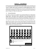
3.2 Board Set-up The 2348-010 elevator boards must be set to identify to the access control system which elevator shaft that it is in, and which floors in the elevator shaft that it is controlling. This programming function is accomplished by the two DIP switches on the elevator control board, with each DIP switch having eight (8) switches in them. The top switch is designated as SW-1 and the bottom switch is designated as SW-2.
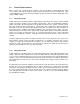
3.2.3 Floor Control Relay Settings Each of the 16 floor control relays on the 2348-010 elevator control board can be set to operate as either a normally open (N.O.) or normally closed (N.C.) device. This is accomplished by the shorting pins located next to each of the relays. SW-1 switch 8 also affects these 16 relays and how they operate. If SW-1 switch 8 is in the OFF position, the 16 elevator button relays on the board will not energize when power is applied to the board.
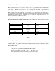
3.3 Switch Settings & Description SW 1 (TOP SWITCH) SWITCH FUNCTION SETTING DESCRIPTION 1–2-3 Elevator Shaft Identification 4 thru 7 Spare OFF Spare switches. Leave in OFF position 8 Relay Activation OFF Floor control relays WILL NOT energize when power is applied to the board. ON Floor control relays WILL energize when power is applied to the board. Identifies which elevator shaft the MASTER board is controlling. See table 3, page 16 for switch matrix. Refer to section 3.2.
Section 4 – Wiring Information Prior to installing wiring to the elevator control board(s), we suggest that you become familiar with the instructions, illustrations, and wiring guidelines in this manual. This will help insure that your installation is performed in an efficient and professional manner. The wiring of the elevator control board(s) is an extremely important and integral part of the overall access control system.
4.2 Control Board Terminal Identification Relay Shorting Pins Terminals 1-18 Terminals 37-54 Power 1 2 3 4 5 6 7 8 Terminals 19-36 1 2 3 4 5 6 7 8 SW 1 Terminals 55-72 SW 2 DOORKING, INC., INGLEWOOD, CA 90301 Title: Date: 2348-010 Control Board 11/03 Dwg. No. M2348-065-5 Rev.
Left Terminals Right Terminals 1 37 2 38 3 39 4 40 5 41 6 42 7 43 8 Not Used 9 44 45 10 46 11 47 12 48 13 49 14 50 15 51 16 52 17 Ground Floor Detect Input 18 19 Not Used 53 54 55 20 Data 1 – Wiegand Input 1 56 21 Data 0 – Wiegand Input 1 57 22 Common – Wiegand Input 1 58 23 Data 1 – Wiegand Input 2 59 24 Data 0 – Wiegand Input 2 60 25 Common – Wiegand Input 2 61 26 62 27 63 28 64 29 30 Not Used 65 66 31 67 32 68 33 69 34 35 36 2348-06
4.3 Power Wiring Block Diagram The elevator control boards must be supplied with 16 VAC power and be properly grounded. Each elevator cabinet can be powered from a single transformer. • Use 18 AWG 600 volt insulted wire for power runs up to 100 feet and 16 AWG 600 volt insulated wire for power runs up to 200 feet. Try to keep all power wire runs as short as possible. • Use a minimum 12 AWG wire for ground.
4.4 Control Wiring Use the figures on the next two pages to assist you with wire connections to the 2348 Elevator Control Board. 4.4.1 Wiegand Wiring Up to eight (8) MASTER 2348-010 elevator control boards can be connected to a single access control system. Each MASTER board can have an additional three (3) elevator control boards connected to it for control of up to 64 floors (16 floor relays on each board). There are two wiegand inputs to the 2348-010 elevator control board.
4.4.3 Lobby Hall Up Call Relay The Lobby Hall Up Call Relay (terminals 69-70) is a special relay that activates when access has been granted and "calls" the elevator car to the lobby or ground floor. • Be sure that the lobby hall call relay is set for Normally Open (N.O.) operation. • SW-2, switch 8 must be in the OFF position for the LOBBY HALL CALL function to operate.
Elevator 1 Elevator 2 2348-010 Board 4 Relays 49-64 2348-010 Board 4 Relays 49-64 7 7 2348-010 Board 3 Relays 33-48 2348-010 Board 3 Relays 33-48 7 7 Elevator Control Electrical Panel 2348-010 Board 2 Relays 17-32 6 1 2 3 4 5 6 7 8 9 10 11 12 13 14 15 16 17 18 1833, 1835, 1837, 1838 Elevator Terminals 2 1 2 3 6 7 WHT GRN BLK WHT GRN BLK 7 8 37 38 39 40 41 42 43 44 45 46 47 48 49 50 51 52 53 54 1 2 3 4 5 6 7 8 9 10 11 12 13 14 15 16 17 18 Relay 16 Relay 15 Relay 14 Relay 13 Relay 12 Re
Access Controller 2348-010 Elevator Control Panel 1 2 3 Elevator Car 1833, 1835, 1837, 1838 Elevator Terminals Elevator Shaft 1 2 3 1833, 1835, 1837, 1838 Controllers or Tracker Board 2348-010 Board 1 Floor Relays 1-16 WHT GRN BLK Elevator Control Panel 4 1 2 3 4 5 6 7 8 9 10 11 12 13 14 15 16 17 18 RED WHT GRN BLK 37 38 39 40 41 42 43 44 45 46 47 48 49 50 51 52 53 54 5 8 Relay 16 Floor Control Relay 15 Floor Control Relay 14 Floor Control Relay 13 Floor Control Relay 12 Floor Con
Section 5 - Elevator Control 5.1 Common Oversights Floor Button Wiring - Remember that the relays for floor control start at the bottom of the board and count UP. Terminals 67 & 68 are for the first or lowest controlled floor. Terminals 65 & 66 are for the second controlled floor; terminals 63 & 64 are for the third controlled floor, etc., etc. First Floor - Remember that the Lobby Level should not be controlled or connected to the elevator control board.
5.2 Software Programming When setting up the Remote Account Manager Software (refer to manual 1835-066), there are some programming steps that must be made in order for the elevator control functions to operate properly: • • • • • • On 1830 series phones - In the System Information Screen, make sure the selection is made for “1833/1835/1837/1838”. If tracker expansion boards are required - To support the reader device inside the elevator car, check the tracker box in the System Information screen.
System Information: Relay Screen Relay Screen - In the Relay Screen, you should label which “system relays” refer to the reader devices inside the elevator car(s). This is for labeling and reference only and does not affect the function or operation of the system. You MUST program the relay address at the relay/elevator screen. System Information: Security Level – Relay / Elevator Relay/Elevator screen - This addresses which system relay is inside each elevator car.
System Information: Security Level Programming of Floor Button Access for building tenants is done in the Security Level Screen. Each resident is assigned to one of the programmed security levels. Within each security level, you select which floor or floors they will have access to and if any time zone restrictions will apply. This does not affect visitor elevator control. • • • • Page 30 Security Level 01 DOES NOT PROVIDE ELEVATOR CONTROL FUNCTIONS.
System Information: Security Level Programming of Floor Button Activation for building tenants is done in the Security Level Screen. Each resident is assigned to one of the programmed Security Levels. Within each security level, you select which floor or floors they will have access to and if any time zone restrictions will apply. This does not affect visitor elevator control • • • Security Level 02, time zone 2 - Programmed for access 7 AM – 9 PM, M-F.
Resident Screen The Resident Screen includes various programming information that will affect the elevator control, both for building tenants (residents) and for visitor access. • • • Page 32 SL (Security Level) - This assigns one of the programmed Security Levels to the resident. The security level will provide control of Floor Level access for the resident. Remember, Security Level 01 will not provide elevator control. FL (Residents Floor) - This identifies which floor the resident lives on.
Resident Screen: Elevator Reference Table The Elevator Reference Table controls two basic functions; which elevator or Elevators will be called down to the lobby (or ground) level when a visitor is granted access, and how long the resident floor control relay will be enabled. • • • Elevator Reference Number - Each resident of building tenant is assigned an Elevator Reference Number. This tells the system which elevator will be called when visitor access is granted.
Page 34 2348-065-E-10-11
Section 6 – Trouble Shooting Before beginning any trouble shooting, review Section 5 in this manual and check all wiring and look for any loose connections. Double check your wiring! Be sure that you have a good VOM (Volt-OhmMeter) to assist you when checking voltages and continuity. The following manuals may be helpful when trouble shooting the access control system. These manuals are available (PDF format) on the DKS Tech Support web site at www.dkaccess.com.
6.2 Programming Trouble Shooting Aids These trouble shooting steps will involve programming commands into the access control system (1833, 1835, 1837 or 1838). These programming steps will cause the access system to wiegand shaft and floor data to the 2348-010 elevator control board(s) so that it can be determined that the corresponding relay(s) on the elevator control board(s) are operating.
6.3 Appendix We strongly recommend that all wiring connections made from the 2348-010 Elevator Control board to the Elevator Control Panel be marked and labeled. The charts on the following pages should be completed for written documentation of the wiring interface. An example is shown below. Be sure that all wires are labeled with a wire number or are color coded. Wire numbers should be used in large systems because of the number of wires that are required.
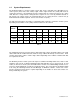
Shaft 1 – Board 1 (Master) Relay No. 16 Board Terminals 37 Floor No. Shaft 1- Board 2 Wire ID Relay No. 16 38 15 39 41 15 43 14 45 13 47 12 49 11 51 10 53 9 55 8 57 7 59 6 61 5 63 4 65 3 67 2 Page 38 69 70 61 63 65 66 1 68 LOBBY CALL 59 64 66 1 57 62 64 2 55 60 62 3 53 58 60 4 51 56 58 5 49 54 56 6 47 52 54 7 45 50 52 8 43 48 50 9 41 46 48 10 39 44 46 11 37 42 44 12 Wire ID 40 42 3 Floor No.
Shaft 1 – Board 3 Relay No. 16 Board Terminals 37 Floor No. Shaft 1- Board 4 Wire ID Relay No. 16 38 15 39 41 15 43 14 45 13 47 12 49 11 51 10 53 9 55 8 57 7 59 6 61 5 63 4 65 3 67 2 2348-065-E-10-11 69 70 61 63 65 66 1 68 LOBBY CALL 59 64 66 1 57 62 64 2 55 60 62 3 53 58 60 4 51 56 58 5 49 54 56 6 47 52 54 7 45 50 52 8 43 48 50 9 41 46 48 10 39 44 46 11 37 42 44 12 Wire ID 40 42 3 Floor No.
Shaft 2 – Board 1 (Master) Relay No. 16 Board Terminals 37 Floor No. Shaft 2- Board 2 Wire ID Relay No. 16 38 15 39 41 15 43 14 45 13 47 12 49 11 51 10 53 9 55 8 57 7 59 6 61 5 63 4 65 3 67 2 Page 40 69 70 61 63 65 66 1 68 LOBBY CALL 59 64 66 1 57 62 64 2 55 60 62 3 53 58 60 4 51 56 58 5 49 54 56 6 47 52 54 7 45 50 52 8 43 48 50 9 41 46 48 10 39 44 46 11 37 42 44 12 Wire ID 40 42 3 Floor No.
Shaft 2 – Board 3 Relay No. 16 Board Terminals 37 Floor No. Shaft 2- Board 4 Wire ID Relay No. 16 38 15 39 41 15 43 14 45 13 47 12 49 11 51 10 53 9 55 8 57 7 59 6 61 5 63 4 65 3 67 2 2348-065-E-10-11 69 70 61 63 65 66 1 68 LOBBY CALL 59 64 66 1 57 62 64 2 55 60 62 3 53 58 60 4 51 56 58 5 49 54 56 6 47 52 54 7 45 50 52 8 43 48 50 9 41 46 48 10 39 44 46 11 37 42 44 12 Wire ID 40 42 3 Floor No.
Shaft 3 – Board 1 (Master) Relay No. 16 Board Terminals 37 Floor No. Shaft 3- Board 2 Wire ID Relay No. 16 38 15 39 41 15 43 14 45 13 47 12 49 11 51 10 53 9 55 8 57 7 59 6 61 5 63 4 65 3 67 2 Page 42 69 70 61 63 65 66 1 68 LOBBY CALL 59 64 66 1 57 62 64 2 55 60 62 3 53 58 60 4 51 56 58 5 49 54 56 6 47 52 54 7 45 50 52 8 43 48 50 9 41 46 48 10 39 44 46 11 37 42 44 12 Wire ID 40 42 3 Floor No.
Shaft 3 – Board 3 Relay No. 16 Board Terminals 37 Floor No. Shaft 3- Board 4 Wire ID Relay No. 16 38 15 39 41 15 43 14 45 13 47 12 49 11 51 10 53 9 55 8 57 7 59 6 61 5 63 4 65 3 67 2 2348-065-E-10-11 69 70 61 63 65 66 1 68 LOBBY CALL 59 64 66 1 57 62 64 2 55 60 62 3 53 58 60 4 51 56 58 5 49 54 56 6 47 52 54 7 45 50 52 8 43 48 50 9 41 46 48 10 39 44 46 11 37 42 44 12 Wire ID 40 42 3 Floor No.
Shaft 4 – Board 1 (Master) Relay No. 16 Board Terminals 37 Floor No. Shaft 4- Board 2 Wire ID Relay No. 16 38 15 39 41 15 43 14 45 13 47 12 49 11 51 10 53 9 55 8 57 7 59 6 61 5 63 4 65 3 67 2 Page 44 69 70 61 63 65 66 1 68 LOBBY CALL 59 64 66 1 57 62 64 2 55 60 62 3 53 58 60 4 51 56 58 5 49 54 56 6 47 52 54 7 45 50 52 8 43 48 50 9 41 46 48 10 39 44 46 11 37 42 44 12 Wire ID 40 42 3 Floor No.
Shaft 4 – Board 3 Relay No. 16 Board Terminals 37 Floor No. Shaft 4- Board 4 Wire ID Relay No. 16 38 15 39 41 15 43 14 45 13 47 12 49 11 51 10 53 9 55 8 57 7 59 6 61 5 63 4 65 3 67 2 2348-065-E-10-11 69 70 61 63 65 66 1 68 LOBBY CALL 59 64 66 1 57 62 64 2 55 60 62 3 53 58 60 4 51 56 58 5 49 54 56 6 47 52 54 7 45 50 52 8 43 48 50 9 41 46 48 10 39 44 46 11 37 42 44 12 Wire ID 40 42 3 Floor No.
Shaft 5 – Board 1 (Master) Relay No. 16 Board Terminals 37 Floor No. Shaft 5- Board 2 Wire ID Relay No. 16 38 15 39 41 15 43 14 45 13 47 12 49 11 51 10 53 9 55 8 57 7 59 6 61 5 63 4 65 3 67 2 Page 46 69 70 61 63 65 66 1 68 LOBBY CALL 59 64 66 1 57 62 64 2 55 60 62 3 53 58 60 4 51 56 58 5 49 54 56 6 47 52 54 7 45 50 52 8 43 48 50 9 41 46 48 10 39 44 46 11 37 42 44 12 Wire ID 40 42 3 Floor No.
Shaft 5 – Board 3 Relay No. 16 Board Terminals 37 Floor No. Shaft 5- Board 4 Wire ID Relay No. 16 38 15 39 41 15 43 14 45 13 47 12 49 11 51 10 53 9 55 8 57 7 59 6 61 5 63 4 65 3 67 2 2348-065-E-10-11 69 70 61 63 65 66 1 68 LOBBY CALL 59 64 66 1 57 62 64 2 55 60 62 3 53 58 60 4 51 56 58 5 49 54 56 6 47 52 54 7 45 50 52 8 43 48 50 9 41 46 48 10 39 44 46 11 37 42 44 12 Wire ID 40 42 3 Floor No.
Shaft 6 – Board 1 (Master) Relay No. 16 Board Terminals 37 Floor No. Shaft 6- Board 2 Wire ID Relay No. 16 38 15 39 41 15 43 14 45 13 47 12 49 11 51 10 53 9 55 8 57 7 59 6 61 5 63 4 65 3 67 2 Page 48 69 70 61 63 65 66 1 68 LOBBY CALL 59 64 66 1 57 62 64 2 55 60 62 3 53 58 60 4 51 56 58 5 49 54 56 6 47 52 54 7 45 50 52 8 43 48 50 9 41 46 48 10 39 44 46 11 37 42 44 12 Wire ID 40 42 3 Floor No.
Shaft 6 – Board 3 Relay No. 16 Board Terminals 37 Floor No. Shaft 6- Board 4 Wire ID Relay No. 16 38 15 39 41 15 43 14 45 13 47 12 49 11 51 10 53 9 55 8 57 7 59 6 61 5 63 4 65 3 67 2 2348-065-E-10-11 69 70 61 63 65 66 1 68 LOBBY CALL 59 64 66 1 57 62 64 2 55 60 62 3 53 58 60 4 51 56 58 5 49 54 56 6 47 52 54 7 45 50 52 8 43 48 50 9 41 46 48 10 39 44 46 11 37 42 44 12 Wire ID 40 42 3 Floor No.
Shaft 7 – Board 1 (Master) Relay No. 16 Board Terminals 37 Floor No. Shaft 7- Board 2 Wire ID Relay No. 16 38 15 39 41 15 43 14 45 13 47 12 49 11 51 10 53 9 55 8 57 7 59 6 61 5 63 4 65 3 67 2 Page 50 69 70 61 63 65 66 1 68 LOBBY CALL 59 64 66 1 57 62 64 2 55 60 62 3 53 58 60 4 51 56 58 5 49 54 56 6 47 52 54 7 45 50 52 8 43 48 50 9 41 46 48 10 39 44 46 11 37 42 44 12 Wire ID 40 42 3 Floor No.
Shaft 7 – Board 3 Relay No. 16 Board Terminals 37 Floor No. Shaft 7- Board 4 Wire ID Relay No. 16 38 15 39 41 15 43 14 45 13 47 12 49 11 51 10 53 9 55 8 57 7 59 6 61 5 63 4 65 3 67 2 2348-065-E-10-11 69 70 61 63 65 66 1 68 LOBBY CALL 59 64 66 1 57 62 64 2 55 60 62 3 53 58 60 4 51 56 58 5 49 54 56 6 47 52 54 7 45 50 52 8 43 48 50 9 41 46 48 10 39 44 46 11 37 42 44 12 Wire ID 40 42 3 Floor No.
Shaft 8 – Board 1 (Master) Relay No. 16 Board Terminals 37 Floor No. Shaft 8- Board 2 Wire ID Relay No. 16 38 15 39 41 15 43 14 45 13 47 12 49 11 51 10 53 9 55 8 57 7 59 6 61 5 63 4 65 3 67 2 Page 52 69 70 61 63 65 66 1 68 LOBBY CALL 59 64 66 1 57 62 64 2 55 60 62 3 53 58 60 4 51 56 58 5 49 54 56 6 47 52 54 7 45 50 52 8 43 48 50 9 41 46 48 10 39 44 46 11 37 42 44 12 Wire ID 40 42 3 Floor No.
Shaft 8 – Board 3 Relay No. 16 Board Terminals 37 Floor No. Shaft 8- Board 4 Wire ID Relay No. 16 38 15 39 41 15 43 14 45 13 47 12 49 11 51 10 53 9 55 8 57 7 59 6 61 5 63 4 65 3 67 2 2348-065-E-10-11 69 70 61 63 65 66 1 68 LOBBY CALL 59 64 66 1 57 62 64 2 55 60 62 3 53 58 60 4 51 56 58 5 49 54 56 6 47 52 54 7 45 50 52 8 43 48 50 9 41 46 48 10 39 44 46 11 37 42 44 12 Wire ID 40 42 3 Floor No.