
Owner`s manual

Page 2
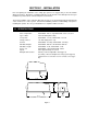
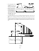
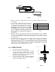
X Y Gate Width
34 30.75 14 Ft.
30 26.50 12 Ft.
26 22.25 10 Ft.
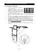
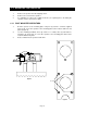
1.2.1 POST MOUNT OPERATOR
1. Screw the two mounting pipes supplied into the
operator mounting plate.
2. Using Table 1 and Figure 2 determine where
POINT C
on the mounting plate / pipe assembly
needs to be located. The location of this
assembly and the
Y
measurement is dependent
on the
X
measurement that you choose.
3.
X
is the measurement from the
center
of the gate
hinge to the
center
of the gate bracket and defines the position of the
A1
and
A2
points.
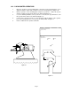
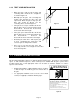
4. Once the location of
POINT C
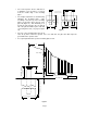
has been determined, construct a form for the
concrete pad according to Figure 3 and place the assembly into the form. Note that
the depth of the pad is determined by soil conditions and local building codes.
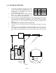
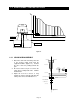
5. Determine the height of the assembly required for your installation. Refer to Figure 4.
6.
IMPORTANT!! Prior to pouring concrete to anchor the mounting plate / pipe
assembly, be sure that POINT C is located correctly and that the mounting
plate is level and at the correct height
.
Conduits can be run into the pad as
required.
7. Let the concrete cure for 48 hours before proceeding with the installation of the gate
operator.
1.2 MOUNTING POST / BASE PLATE INSTALLATION
Table 1
Figure 2
12 min
9 3/4
X
Gate Closed
Gate Open
90°
Fence
Pilaster
A2
A1
Point C is the
intersection of the A1-A2
line and the output shaft.
See Detail A.
Y
A1-A2 Line
Point C
Mounting
Plate
Detail A
Output
Shaft
Gate
Bracket