
Owner`s manual

Page 12
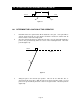
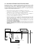
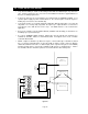
4. Determine where the operator output shaft will be placed. With a string, connect
points A1 and A2 and extend this line beyond A2. The operator shaft must be on the
A1-A2 line, at least 12 inches away from the gate (Figure 21).
NOTE: Point C can be located anywhere on the A1-A2 line. However, the farther
away from the gate point C is made, the longer the operator connecting arm will be.
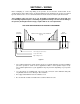
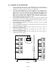
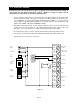
5. Install the mounting plate / pipe assembly (or concrete base plate) in accordance with
instructions detailed in this manual. Be sure that your mounting plate/ pipe assembly,
or concrete base plate, and pad is located so that the operator output shaft will
intersect the A1-A2 line at the point that you have selected.
NOTE: Mount the plate / pipe assembly so that the operator will be square to
the fence line and not parallel to the gate when it is in the open position
.
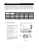
1.6.2 ARM LENGTH CALCULATIONS
After the operator has been installed, use the following steps to determine the correct crank arm and
connecting arm lengths for the installation.
1. Measure the distance from point A1 to point A2. Divide this measurement by 2. The
result is the length of the crank arm assembly from the operator output shaft to the
pivot point on the connector assembly.
2. Measure the distance from point A1 to the operator output shaft. Subtract from this
measurement the length of the crank arm assembly that was determined in step 1.
The result is the length of the connecting arm.
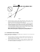
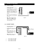
Figure 21
FENCE
A1
A2
A1-A2 LINE