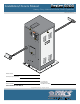
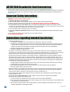
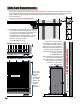
Installation/Owner’s Manual Series 9200 Heavy-Duty Vehicular Slide Gate Operator Use this manual for circuit board 4404-010 Revision A or higher. CA CO NF AN OR SI/U MS L-32TO CE 5 RT CS IFI A C2 ED 2.2 TO NO CU . 24 LA 7 R S GA N/ VE HI CL 533 82 AS TE MO DE L SE OP ER HP RI AL AT OR WA R 9210-065-H-2-13 NI NG VO LT S AM PS MA X GA TE LO AD Do orKi ng , Inc .
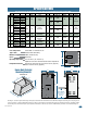
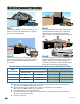
SPECIFICATIONS Use this manual for the 9200 series operators with circuit board 4404-010 Rev A or higher ONLY. 9245 9240 9235 9230 9220 9210 Horse Power Volt/Phase Amps 115 / 1 208 / 1 230 / 1 208 / 3 230 / 3 208 / 1 230 / 1 208 / 3 230 / 3 208 / 3 230 / 3 208 / 3 230 / 3 208 / 3 230 / 3 208 / 1 230 / 1 9.7 5.0 4.9 3.3 3.4 11.5 11.7 6.6 6.2 9.8 9.6 12.8 12.6 9.8 9.6 12.8 12.6 1 2 3 3 3 3 Gearbox Mech.
TABLE OF CONTENTS SPECIFICATIONS 1 Gate Construction 4 Important Safety Instructions 4 Instructions regarding intended installation: 4 Important Notices 5 UL325 Entrapment Protection 6 Glossary 7 Slide Gate Requirements 8 Slide Gate Protection 9 SECTION 1 - INSTALLATION 1.1 Gate Hardware 10 1.2 Underground Conduit Requirements 10 1.3 Installation Options, Gate Types 1.4 Installation #1 1.5 Installation #2, Chain Tray Kit 11-12 13 14-15 1.6 Chain Installation 16 1.
TABLE OF CONTENTS 3.4 Inherent Reverse Sensor Adjustment 23 3.5 Current Sensor Adjustment 23 3.6 AC Module Adjustment 24 SECTION 4 - ENTRAPMENT AND SAFETY PROTECTION 4.1 UL 325 Terminal Description 4.2 Secondary Entrapment Protection Device Locations 4.3 Loop Detector Wiring SECTION 5 - MAIN TERMINAL WIRING 25 25 26-27 28 29 5.1 Main Terminal Description 29 5.2 Control Wiring for Single/Primary Operator 30 5.3 Auxiliary Device Wiring 31 5.
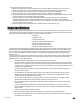
ASTM F2200 Standard for Gate Construction Vehicular gates should be constructed and installed in accordance with ASTM F2200; Standard Specification for Automated Vehicular Gate Construction. For a copy of this standard, contact ASTM directly at 610-832-9585; service@astm.org; or www.astm.org. Important Safety Instructions WARNING - To reduce the risk of injury or death: 1. READ AND FOLLOW ALL INSTRUCTIONS. 2. Never let children operate or play with gate controls. Keep the remote control away from children.
• For gate operators utilizing contact sensors: 1. One or more contact sensors shall be located where the risk of entrapment or obstruction exist, such as at the leading edge, trailing edge, and post mounted both inside and outside of a vehicular horizontal slide gate. 2. One or more contact sensors shall be located at the bottom edge of a vehicular vertical lift gate. 3. One or more contact sensors shall be located at the pinch point of a vehicular vertical pivot gate. 4.
UL325 Entrapment Protection Class I Class II A vehicular gate operator (or system) intended for use in a home of one-to four single family dwelling, or a garage or parking area associated therewith. A vehicular gate operator (or system) intended for use in a commercial location or building such as a multi-family housing unit (five or more single family units) hotel, garages, retail store or other building servicing the general public.
Glossary GATE - A moving barrier such as a swinging, sliding, raising, lowering, or the like, barrier, that is a stand-alone passage barrier or is that portion of a wall or fence system that controls entrance and/or egress by persons or vehicles and completes the perimeter of a defined area. RESIDENTIAL VEHICULAR GATE OPERATOR – CLASS I - A vehicular gate operator (or system) intended for use in a home of one-to four single family dwelling, or garage or parking area associated therewith.
Slide Gate Requirements The operator is intended for installation only on gates used for vehicles. Pedestrians must be supplied with a separate access opening. The pedestrian access opening shall be designed to promote pedestrian usage. Locate the gate such that persons will not come in contact with the vehicular gate during the entire path of travel of the vehicular gate. (ref. UL 325 56.8.4.b) Adjacent fence that covers open gate position.
Slide Gate Protection Entrapment protection devices are required to reduce the risk of injury. Install sensors where the risk of entrapment or obstruction exists while gate is moving. Individual requirements will vary. Contact Sensor (Reversing Edges) Warning Signs A Installed on the fence to help minimize the potential of 2 Fence entrapment between the gate and fence. A filler post or barrier may need to be installed between fence and gate.
SECTION 1 - INSTALLATION Prior to beginning the installation of the slide gate operator, we suggest that you become familiar with the instructions, illustrations, and wiring guide-lines in this manual. This will help insure that your installation is performed in an efficient and professional manner compliant with UL 325 safety and ASTM F2200 construction standards. The proper installation of the vehicular slide gate operator is an extremely important and integral part of the overall access control system.
1.3 Installation Options The operator MUST be level. See the next page for typical gate types. We suggest that you contact the local building department to determine the required depth of the concrete pad since soil conditions and code requirements vary from city to city. #1 - Operator Mounted Directly on a Concrete Pad Typically used when gates are less than 20 feet in length and under 2000 lbs. in weight. V-rail v-wheel gate type shown.
1.3 Continued Gate Types • Steel or Aluminum. • 8,000 lb Max. Weight per Gate (9240, 9245). He -D y v a u rn O ty e am n C tal an v tile so ate ed nd me g for om c and d tan s ting n y tra rec oun CONFORMS ANSI/UL-325 TO CLASS NO. NG OPERATOR HP VOLTS GATE LOAD DoorKing, MOVING SERIOUS PHASE 60 Operate and free Hz Inc., Inglewood, CA B ut y o ra xF GATE INJURY CAN gate of people CAUSE only Do OR when and or not allow DEATH operate obstructions.
The operator is heavy. Two persons are required when handling the operator during installation. 1.4 Installation #1 Operator Mounted Directly on a Concrete Pad Tip: Trace the base plate of the operator on a piece of masonite (Not provided) and make a template to help locate where the conduit runs will be positioned in the concrete pad. Ele CO NFO AN RM SI/U S L-3 TO CAN CER 25 /CS TIF A C22IED VE .2 TO HIC NO .
1.5 Installation #2 Operator Mounted on the Heavy-Duty Pedestal Mounting Stand The operator is heavy. Two persons are required when handling the operator during installation. Caution: DO NOT lay the operator on it’s side or oil will leak out of the gear reducer. 1. Assemble and install the pedestal mounting stand kit (P/N 9200-135) on the concrete pad, then mount the operator to it. Follow the instructions that came with the pedestal mounting stand kit for assembly of the stand. 2.
1.5 Continued - Chain Tray Kit Installing the Chain Tray Kit A chain tray is recommended for gates longer than 20 ft. to support the weight of the chain. DoorKing offers a chain tray kit in sections to fit any length gate. (DoorKing P/N 2601-270 10 Ft. section) Chain Tray Supporting Bracket (Facing up) Ft. Carriage Bolts Se gm ent Weep Hole Chain Tray Segments Connection 10 Ft.
1.6 Chain Installation 1 Operator MUST be parallel to gate! Note: Be sure to follow all 3 guidelines. Installing the chain in any other manner will cause excessive noise, chain idler wheel wear and chain stretching.
1.7 Installation of Warning Signs This DoorKing Slide Gate Operator is shipped with two warning signs. The purpose of the warning sign is to alert uninformed persons, and to remind persons familiar with the gate system, that a possible hazard exists so that appropriate action can be taken to avoid the hazard or to reduce exposure to the hazard. See page 9 for typical placement of signs.
2.2 High Voltage Terminal Connection • Route incoming AC power wire through the high voltage conduit and run wire in the operator electronic box as shown. • Be sure wiring is installed in accordance with local codes. Be sure to color code all wiring. • It is recommended that a surge suppressor be installed on the high voltage power lines to help protect the operator and circuit board from surges and power fluctuations. Dual Operators • Dual operators (Primary/Secondary) require AC power to EACH operator.
SECTION 3 - ADJUSTMENTS The switch settings and adjustments in this chapter should be made after your installation and wiring to the operator(s) is complete. Whenever any of the programming switches on the circuit board are changed, power must be shut-off, and then turned back on for the new setting to take effect. 3.1 Circuit Board Description and Adjustments LEDs Indicates that low voltage power is applied to the circuit board.
3.2 DIP-Switch SW 1 and SW 2 Settings The two DIP-switches located on the circuit board are used to program the operator to operate in various modes and to turn on or off various operating features. Whenever a switch setting is changed, power to the operator must be turned OFF and then turned back on for the new setting to take affect. Check and review ALL switch settings prior to applying power to the operator. 1 2 3 4 Typical Settings SW 1 - Right 8 Switches ON ON SW 2 is Upside-Down on Circuit Board.
3.2 Continued The two DIP-switches located on the circuit board (Upside-Down ) are used to program the operator to operate in various modes and to turn on or off various operating features. Whenever a switch setting is changed, power to the operator must be turned OFF and then turned back on for the new setting to take affect. Check and review ALL switch settings prior to applying power to the operator.
Check the polarity of “Three Phase” operator ONLY: Position the gate half way open. Give open command and while gate is opening, activate the appropriate limit switch with your finger. Gate should STOP. If it does not, activate the other limit switch. If this STOPS the gate, AC power wires must be changed (Reverse the connection of any 2 wires and re-check limits). 3.
3.4 Inherent Reverse Sensors Adjustment This vehicular gate operator is equipped with an inherent adjustable reversing sensor (Type A) used as the primary entrapment protection system according to UL 325 standards. The gate will reverse direction after “physically” encountering an obstruction in either the opening or closing gate cycle.
3.6 AC Module Adjustment The 9220, 9230, 9235, 9240 and 9245 models are equipped with an AC module that allows you to adjust the speed of the gate from 0 to 2 feet per second. To adjust the speed, simply rotate the speed control knob clockwise to increase the gate speed, or counter-clockwise to decrease the gate speed. The digital readout on the AC module will display the gate speed. L1 L2 L3 L1 L2/N B- B+ B- B+ L1 PE Min Max Speed 1.5 ft/s .5 ft/s .5 ft/s 1.
SECTION 4 - ENTRAPMENT AND SAFETY PROTECTION Secondary Entrapment Protection Devices: In addition to the inherent reversing sensor system, the 9200 Series has a 6-pin UL 325 terminal for the connection of photo sensors-Type B1 and reversing edges-Type B2 secondary entrapment protection devices required by UL 325 standards. Entrapment protection devices must be installed to reduce the risk of injury. Install these devices where the risk of entrapment or obstruction exists while the gate is moving.
4.2 Secondary Entrapment Protection Device Locations Typical UL Photo Sensor mounting height and distance away from gate. UL sensor mounted on wall. 5” or Less Gate Frame 5” or Less UL sensor mounted on post. Inside Property Filler Post or Barrier Non-Secure Side Outside Property Reversing Edge (Open Contact Sensor) Gate Frame Secure Side If the distance between the gate and wall is greater than 2 1/4”. Wall 21” Typical Photo sensors may be installed on either side of gate frame.
Wireless Reverse Edge Sample Setup - Single Receiver Edge Transmitter Normally Open Filler Post Note: Install reversing edges on all the gate support posts or filler post in this area (e.g. cantilever gate installations, See below). 9 V battery operated transmitter mounted on gate. Normally Open Common OPEN Entrapment Sensor Filler Post (If necessary) Opening-Direction Reversing Edge Opening-Direction Reversing Edge (If filler post is used).
4.3 Loop Detector Wiring To help protect the operator from accidentally closing on vehicles in the gate’s path, DoorKing highly recommends that loops and loop detectors be installed. Loops are laid underneath, cut into asphalt or concrete driveways or buried beneath gravel and earth driveways. A loop detection system will sense a vehicle like a metal detector and send a signal to the gate operator preventing the gate from automatically opening or closing on a vehicle when it is in the gate’s path.
SECTION 5 - MAIN TERMINAL WIRING P7 NO Auxiliary Common Terminal 4404 NC Connect any low voltage common wire to these 2 terminals. Used in conjunction with the circuit board inherent reversing sensors. See page 23 for further information. Low Voltage Common Low Voltage Common 2 1 Full Open 24 VAC - 250 mamp. max.
5.2 Control Wiring for Single/Primary Operator Important: Controls must be far enough from the gate so that the user is prevented from coming in contact with the gate while operating the controls. Outdoor or easily accessible controls should have a security feature to prevent unauthorized use. P7 NO NC 4404 Auxiliary Common Terminal Connect any common wire to these 2 terminals.
5.3 Auxiliary Device Wiring P7 NO NC 4404-010 4404 20 19 18 17 16 15 14 13 12 11 10 9 8 7 6 5 4 3 2 1 Blue Alarm Reset Terminal Red Alarm Output Terminal White Common Terminal Remote Alarm Reset Station (DoorKing P/N 1404-080 Only) MUST be mounted in the line-of-sight of the gate operator. Gate Tracker - DoorKing Access Control System (Model 1833, 1835, 1837 or 1838) tracker system can be connected.
5.4 Bi-Parting Gates Wiring - Dual Gate Operators P7 NO 1 2 3 4 5 6 • Requires AC power to each operator. UL 325 Terminal NC 4404-010 4404 • Both operator DIP-switches must be set. • Connect all control devices, auxiliary devices and loops to the primary operator only. Primary Operator 8 Brown 3-Wire Receiver Com Relay Note: 4-wire radio receiver, or any other opening devices get wired to primary operator ONLY, as shown on page 30.
SECTION 6 - OPERATING INSTRUCTIONS IMPORTANT SAFETY INSTRUCTIONS WARNING - To reduce the risk of injury or death: 1. READ AND FOLLOW ALL INSTRUCTIONS. 2. Never let children operate or play with gate controls. Keep the remote control away from children. 3. Always keep people and objects away from gate. NO ONE SHOULD CROSS THE PATH OF THE MOVING GATE. 4. Test the operator monthly. The gate MUST reverse on contact with a rigid object or stop or reverse when an object activates the non-contact sensors.
6.2 Shutdown Conditions Under various entrapment conditions the operator will assume either a soft or hard (alarm) shutdown. To determine what type of reset action is required, you will need to understand how the different entrapment conditions affect the gate operator. Soft Shutdown This occurs in various situations where the inherent or secondary entrapment protection devices have been activated.
6.3 Manual Gate Operation Caution: Never attempt to manually operate any gate until you have verified that power to the operator has been shut-off. 2 1 Insert the supplied manual hand crank into the access hole until it engages with the motor shaft. Turn the crank to open the gate. 9235, 9245 mechanical disc brake model operators MUST also have the disc brake manually released before manually cranking the hand crank (See M below).
SECTION 7 - MAINTENANCE AND TROUBLESHOOTING Inspection and service of this gate operator by a qualified technician should be performed anytime a malfunction is observed or suspected. High cycle usage may require more frequent service checks. 7.1 Maintenance When servicing the gate operator, always check any secondary (external) reversing devices (loops, photocells, etc.) for proper operation.
7.2 Built-In Diagnostic Tests This gate operator is designed with built-in diagnostics that will alert you to potential or existing problems that the microprocessor has detected. Specific fault conditions are checked and the operator will signal that a fault exist through the built-in alarm. Constant alarm is heard when power is applied: This indicates that the limit switch wire harness is not connected to the circuit board.
Symptom Operator will not run. Power LED is OFF. 38 Possible Solution(s) • Check that AC power to the operator is turned ON. • Transformer may be overheated. Turn power off and allow board to cool for several minutes then retest. Check for low VAC power and low voltage shorts. • Check for VAC at high voltage input terminal. If voltage measures 0, check the incoming power wires or replace the circuit board. Gate opens a short distance, then stops and reverses.
7.4 Accessory Items The following accessory items are available for the series 9200 slide gate operators. Contact Sensors - For use as a secondary entrapment protection device. Miller Edge, Inc., MGO20, MGR20, MGS20 Chain Tray Kit - 10 Ft. section. Sections connect together to fit any length gate. P/N 2601-270 Pedestal Mounting Stand - Heavy-duty pedestal mounting stand for the 9200 series operator. P/N 9200-135 Heater and Fan Kit - Recommended for cold weather climates.
Installation/Owner’s Manual Series 9200 Heavy-Duty Vehicular Slide Gate Operator Use this manual for circuit board 4404-010 Revision A or higher. 9210-065-H-2-13 www.doorking.com DoorKing, Inc. 120 Glasgow Avenue Inglewood, California 90301 U.S.A. Phone: 310-645-0023 Fax: 310-641-1586 Copyright 2009 DoorKing, Inc. All rights reserved.