Owner’s Manual Model 9210, 9220, 9230 Vehicular Slide Gate Operators DoorKing, Inc. 120 Glasgow Avenue Inglewood, California 90301 U.S.A. Phone: 310-645-0023 Fax: 310-641-1586 www.doorking.com P/N 9210-065 Rev H, 8/08 Copyright 2001 DoorKing, Inc. All rights reserved.
Page 2 9210-065-H-8-08
Use this manual with the following models only. Models 9210-080, 9210-081, 9210-082, 9210-083, 9210-084, 9210-086, 9210-087, 9210-088, 9210-089, 9210-090, 9210-091, 9220-080, 9220-081, 9220-082, 9220-083, 9220-084, 9220-085, 9220-086, 9220-087, 9230-080, 9230-081 with circuit board 4404-010. DoorKing, Inc. reserves the right to make changes in the products described in this manual without notice and without obligation of DoorKing, Inc. to notify any persons of any such revisions or changes.
Glossary GATE: A moving barrier such as a swinging, sliding, raising, lowering, or the like, barrier, that is a stand-alone passage barrier or is that portion of a wall or fence system that controls entrance and/or egress by persons or vehicles and completes the perimeter of a defined area. RESIDENTIAL VEHICULAR GATE OPERATOR – CLASS I: A vehicular gate operator (or system) intended for use in a home of one-to four single family dwelling, or garage or parking area associated therewith.
Entrapment Protection Protection Against Entrapment Gate Operator Category Horizontal Slide, Vertical Lift, Vertical Pivot Swing and Vertical Barrier (arm) Usage Class Primary Secondary Primary Secondary Vehicular I and II A B1, B2 or D A or C A, B1, B2, C or D Vehicular III A, B1 or B2 A, B1, B2, D or E A, B1, B2 or C A, B1, B2, C, D or E Vehicular IV A, B1, B2 or D A, B1, B2, D or E A, B1, B2, C or D A, B1, B2, C, D or E TYPE A: TYPE B1: TYPE B2: TYPE C: TYPE D: TYPE E: 9210-065
Important Notices Vehicular gate operator products provide convenience and security. However, gate operators must use high levels of force to move gates and most people underestimate the power of these systems and do not realize the potential hazards associated with an incorrectly designed or installed system.
Important Safety Instructions WARNING - To reduce the risk of injury or death: 1. 2. 3. 4. 5. 6. 7. 8. READ AND FOLLOW ALL INSTRUCTIONS. Never let children operate or play with gate controls. Keep the remote control away from children. Always keep people and objects away from gate. NO ONE SHOULD CROSS THE PATH OF THE MOVING GATE. Test the operator monthly.
Instructions regarding intended installation: Install the gate operator only if: 1. The operator is appropriate for the construction of the gate and the usage class of the gate. 2. All openings of a horizontal slide gate are guarded or screened from the bottom of the gate to a minimum of 4 feet (1.22 m) above the ground to prevent a 2 ¼ inch (57.2 mm) diameter sphere from passing through the openings anywhere in the gate, and in that portion of the adjacent fence that the gate covers in the open position.
For gate operators utilizing contact sensors: 1. 2. 3. 4. 5. 7. One or more contact sensors shall be located where the risk of entrapment or obstruction exist, such as at the leading edge, trailing edge, and post mounted both inside and outside of a vehicular horizontal slide gate. One or more contact sensors shall be located at the bottom edge of a vehicular vertical lift gate. One or more contact sensors shall be located at the pinch point of a vehicular vertical pivot gate.
Slide Gate Requirements All openings of a horizontal slide gate are guarded or screened from the bottom of the gate to a minimum of four (4) feet (1.22 m) above the ground to prevent a 2 1/4 inch (57.2 mm) diameter sphere from passing through the openings anywhere in the gate and in that portion of the adjacent fence that the gate covers in the open position. (ref. UL325 56.8.4.a.2 and ASTM F2200 6.1.2) The operator is intended for installation only on gates used for vehicles.
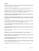
Slide Gate Protection 1 Loops to help minimize the potential of the gate to close when a vehicle is present. Number and placement of loops is dependent on the application. 2 Contact sensor installed on the fence to help minimize the potential of entrapment between the gate and fence. 1 Reverse Loop 6 5 Fence 2 Pedestrian Access 3 4 Fence 5 3 Non-contact sensor to help minimize the potential of the gate closing on vehicular or other traffic that loops cannot sense.
Table of Contents Section 1 – Installation 1.1 Specifications ...........................................................................................................................................15 1.2 Mounting Options .....................................................................................................................................16 1.3 Chain Guide Adjustment.......................................................................................................................
Section 4 – Operating Instructions 4.1 Power and Reset Switches ......................................................................................................................41 4.2 Shutdown Conditions 4.3 4.2.1 Soft Shutdown ..........................................................................................................................42 4.2.2 Resetting a Soft Shutdown.......................................................................................................42 4.2.
Page 14 9210-065-H-8-08
SECTION 1 - INSTALLATION Prior to beginning the installation of the slide gate operator, we suggest that you become familiar with the instructions, illustrations, and wiring guide-lines in this manual. This will help insure that your installation is performed in an efficient and professional manner. The proper installation of the vehicular slide gate operator is an extremely important and integral part of the overall access control system.
1.2 Mounting Options The 9210, 9220 and 9230 vehicular gate operators are designed to be mounted on the optional mounting stand (p/n 9200-135) or directly to a concrete pad. The mounting stand option is recommended if the gate length exceeds 30 feet since this mounting method will allow a “chain rest” to be mounted on the gate. Pad mounting is typically used with gates that are less than 30 feet in length. Requires use of the pad mounting plate that is included with the operator.
1.3 Chain Guide Adjustment After determining which mounting method is to be used (pad or mounting stand), adjust the chain guides according to the mounting method being used. To gain access to the inside of the operator, remove three hex-head nuts from the left side of the control panel housing. Pull the housing out and away. OPEN For pad mounted operators, remove the UPPER hole knockouts from each side of the operator. Adjust the chain guides as shown.
1.4 Pad Mount Installation 1. Construct a form for the mounting pad according to the specifications shown below. Be sure to level the top edge of the form and that the top of the form is a minimum of four (4) inches above ground level. We suggest that you contact the local building department to determine the required depth of the pad since soil conditions and code requirements vary from city to city. 2. Set conduits, reinforcing bars and/or wire mesh if required.
bolts in the concrete. Sleeve anchors should be used to secure the operator to the pad. This allows greater flexibility in positioning the operator on the pad. 4. Allow the pad to cure for 48 hours before removing the forms or mounting the operator. 5. Once the pad has cured, place the operator / mounting plate on the pad in the proper position; 4-inches from the front and sides of the pad and 1-inch from the rear of the pad. The operator mounting plate must be parallel to the gate.
1.5 Mounting Stand Installation 1. Construct a form for the mounting pad according to the specifications shown below. Be sure to level the top edge of the form and that the top of the form is a minimum of four (4) inches above ground level. We suggest that you contact the local building department to determine the required depth of the pad since soil conditions and code requirements vary from city to city. 2. Set conduits, reinforcing bars and/or wire mesh if required.
3. Mix the concrete according to the manufacturers instructions. Pour the mixture into the form and tamp. Level and finish the surface after pouring is complete. Do not set anchor bolts in the concrete. Sleeve anchors should be used to secure the operator to the pad. This allows greater flexibility in positioning the operator on the pad. 4. Allow the pad to cure for 48 hours before removing the forms or mounting the operator. 5.
1.6 Chain Installation 1. Secure the chain brackets to each end of the gate so that the brackets will be level with the chain where it exits the operator. Brackets should be attached to the inside of the frame so that the chain bolts, when attached, do not protrude beyond the frame of the gate. 2. Route the chain through the gate operator. 3. Attach the chain to the chain bolts using the master links supplied, and then attach the chain bolts to the chain brackets using the hardware supplied.
20 10.
1.7 Warning Sign Installation This DoorKing slide gate operator is shipped with two warning signs. The purpose of the warning signs is to alert uniformed persons, and to remind persons familiar with the system, that a potential hazard may exist so that appropriate action can be taken to avoid the hazard or to reduce exposure to the hazard. 1. Permanently install the supplied warning signs in locations so that the signs are visible by persons on both sides of the gate. 2.
SECTION 2 – WIRING Before attempting to connect any wiring to the operator, be sure that the circuit breaker in the electrical panel is in the OFF position. Permanent wiring must be installed to the operator as required by local electrical codes. It is recommended that such work be performed by a licensed electrical contractor.
2.1 High Voltage Connections Use the table below to determine high voltage wire size requirements. The distance shown in the chart is measured in feet from the operator to the power source. If power wiring is greater than the maximum distance shown, it is recommended that a service feeder be installed. When large gauge wire is used, a separate junction box must be installed for the operator connection. The wire table is based on stranded copper wire.
2.2 Control Wiring Controls must be far enough from the gate so that the user is prevented from coming in contact with the gate while operating the controls. Outdoor or easily accessible controls should have a security feature to prevent unauthorized use. Fence C Roadway D A C B Open contact sensor placed on fence. D 4404-010 Circuit Board 1 Receiver 3 A Open direction non-contact sensor. B Close direction non-contact sensor. 1 C Open direction contact sensor.
2.3 Loop Detector Wiring Loops and loop detectors must be installed with this gate operator to prevent the gate from accidentally closing on vehicles that may be in the path of the gate. 8 Loops and loop detectors MUST be installed with this gate operator to help prevent the gate from accidentally closing on vehicular traffic. 8 Loop detector wiring is shown for DoorKing plug-in loop detectors only.
2.4 Auxiliary Device Wiring 1 The auxiliary stop switch will stop a moving gate when activated or will prevent the gate operator from starting when activat ed. Note that this input is normally open and that a switch closure is required to activate the stop function . Because of this, the auxiliary stop shown must NEVER be used as a safety interlock device. 2 Jumper is placed across terminals 7 and 8 ONLY WHEN THE AUXILIARY STOP INPUT IS USED.
2.5 Primary – Secondary (Bi-Parting) Gate Wiring The interface wiring between the two operators requires seven (4) wires (18 AWG minimum) for control and secondary entrapment protection device connection. Each operator must be connected to its own power source as described in section 2.1. D E A B C D E 1 Connect the Primary / Secondary interconnection wiring as shown. Wire colors are based on DoorKing interconnection cable (P/N 2600-75x).
2.6 Terminal Identification and Description 2.6.1 Main Terminal (P1) 1. 2. 3. 4. 5. 6. 7. 8. 9. 10. 11. 12. 13. 14. 15. 16. 17. 18. 19. 20. LOW VOLTAGE COMMON OPEN / CLOSE INPUT When gate is closed, input will open gate to full position. When gate is open and auto close timer is turned on, input will re-set and hold timer. When gate is open and auto close timer is turned off, input will close gate. When gate is closing, input will reverse gate.
2.6.2 Limit Switch Connector The limit switch connector is located at the upper left-hand corner of the 4404 circuit board and provides input to the circuit board from the limit switches. 1. 2. 3. 4. 5. 6. 7. 8. FULL LIMIT SLOW DOWN PARTIAL LIMIT SLOW DOWN FULL LIMIT LIMIT ENABLE LIMIT COMMON LIMIT COMMON 2.6.3 Reversing Device Connector External entrapment prevention devices are connected here. 1. OPEN PHOTO-BEAM This input is only active when the gate is in the opening cycle.
SECTION 3 - ADJUSTMENTS The switch settings and adjustments in this chapter should be made after your installation and wiring to the operator(s) is complete. Whenever any of the programming switches on the circuit board are changed, power must be shut-off, and then turned back on for the new setting to take effect. 3.1 Circuit Board Adjustments Set the DIP-switches on the circuit board to the desired setting. See switch-setting charts in section 3.2.
3.2 Switch Settings The two DIP-switches located on the circuit board are used to program the operator to operate in various modes and to turn on or off various operating features. Whenever a switch setting is changed, power to the operator must be turned OFF and then turned back on for the new setting to take affect. Check and review ALL switch settings prior to applying power to the operator. CAUTION: Switches on the circuit board are numbered right to left, not left to right.
3.2.1 SW 1 (Right Switch) Description and Function Switch 1: Set so that the operator cycles open upon initial power up and open command. If the operator cycles close, turn power off and change the setting on this switch. Switch 2: Turns the auto close timer on or off. Set from 1 to 23 seconds. Loops and loop detectors, photoelectric cells, or other like devices must be installed when the auto close timer is used to prevent the gate from closing on vehicular traffic.
3.3 Limit Adjustment 3.3.1 Limit Adjustment for 9210 Operator 1. 2. 3. 4. 5. 6. Turn power off. Push the lock plate handle down to adjust the Open and Close limit nuts. After adjusting the limit-nuts, be sure that the lock-plate is engaged in the slots on the limit-nuts to prevent them from slipping. Turn power on and activate the gate operator. Re-adjust the limit-nuts as necessary for full-open and full-close gate travel.
3.3.2 Limit Adjustment for 9220, 9230 Operators The 9220 and 9230 operators utilize a pair of switches at the open and close positions. The first switch is the slow-down switch and the second switch is the limit switch. The slow-down switch is adjustable so that you can increase or decrease when the slow-down is initiated. For example, on heavy gates it is desirable to increase the slow-down distance to provide the operator more time to slow-down and stop the gate. 1. 2. 3. 4. Turn power off.
3.4 Reverse Adjustment This vehicular gate operator is equipped with an inherent (Type A) entrapment sensing system. This system will sense an obstruction in either the opening or closing gate cycles and will cause the gate to reverse direction should an obstruction be encountered. For this system to function correctly, the gate must be properly installed and work freely in both directions. A good set of ball bearing wheels (or rollers) is essential for proper slide gate operation. 1. Refer to section 3.
Speed Control (9220, 9230 Only) L1 L2 L3 B- 1.5 ft/s 0 ft/s 2 ft/s V W PE 17 .5 ft/s U 3.6 B+ 1.0 1 ft/s 1 2 5 6 11 13A 13B 13E 25 The models 9220 and 9230 are equipped with a speed control module that allows you to adjust the speed of the gate from 1/2 to 2 Ft./ Sec. To adjust the speed, simply rotate the speed control knob clockwise to increase the gate speed, or counter clockwise to decrease the gate speed. The digital readout on the speed controller will display the gate speed.
Page 40 9210-065-H-8-08
SECTION 4 – OPERATING INSTRUCTIONS WARNING - To reduce the risk of injury or death: 1. 2. 3. 4. 5. 6. 7. 8. 4.1 READ AND FOLLOW ALL INSTRUCTIONS. Never let children operate or play with gate controls. Keep the remote control away from children. Always keep people and objects away from gate. NO ONE SHOULD CROSS THE PATH OF THE MOVING GATE Test the operator monthly. The gate MUST reverse on contact with a rigid object or stop or reverse when an object activates the non-contact sensors.
4.2 Shutdown Conditions Under various entrapment conditions the operator will assume either a soft or hard shutdown (alarm) condition. To determine what type of reset action is required, you will need to understand how the different entrapment conditions affect the gate operator. 4.2.1 Soft Shutdown This occurs in various situations where the inherent or secondary entrapment protection devices have been activated.
4.2.3 Hard Shutdown A hard shutdown condition occurs when the inherent entrapment protection system has sensed two consecutive obstructions before the gate reaches the full open or full closed position. It can also be an indication that the gate is too heavy or that the gate hardware (wheels, rollers) is in poor condition and needs to be corrected. Do not reduce the operator reversing sensitivity in an attempt to correct for a poorly designed gate or for hardware that is in need of repair.
4.3 Manual Gate Operation This operator is equipped with a manual system that will allow the gate to be cranked open in the event of a power outage or equipment failure. NOTE: Never attempt to manually open any gate with an operator attached to it until you have verified that power to the operator has been shut-off. 1. Unlock the manual release access panel located on the top of the gate operator and open it.
SECTION 5 – MAINTENANCE AND TROUBLESHOOTING Inspection and service of this gate operator by a qualified technician should be performed anytime a malfunction is observed or suspected. High cycle usage may require more frequent service checks. 5.1 Maintenance When servicing the gate operator, always check any secondary (external) reversing devices (loops, photo eyes, etc.) for proper operation.
5.2 Operator Diagnostics This gate operator is designed with built-in diagnostics that will alert you to potential or existing problems that the microprocessor has detected. Specific fault conditions are checked and the operator will signal that a fault exist through the built-in alarm. Constant tone is heard when power is applied: This indicates that the limit switch wire harness is not connected to the circuit board.
5.3 Trouble Shooting Have a good VOM meter to check voltages and continuity. A Meg-Ohm meter capable of checking up to 500 meg-ohms of resistance is necessary to properly check the integrity of the ground loops. When a malfunction occurs, isolate the problem to one of three areas: 1) the operator, 2) the loop system, 3) the keying devices. Use caution when checking high voltage terminals, motor capacitor and the motor. 1. Check the input indicator LEDs.
Gate opens a short distance, then stops and reverses. Gate opens but will not close. Gate closes but will not open. Gate starts to close, then reverses to open. Gate closes and then re-opens. Entrapment alarm is sounding. Operator will not run. Entrapment alarm sounds a short beep every 5 seconds. Entrapment alarm activates when power is applied and operator will not run. Operator runs for 1 second and stops, two short beeps are heard.
5.4 Accessories The following accessory items can be used with the model 9210 / 9230 slide gate operator. Contact Sensor Photo Cell Loop Detector Loop Wire Pre-Fab Loops Loop Test Meter Control Station Time Clock Surge Devices Gate Scale Speed Bumps Mounting Stand Remote Reset Traffic Signal 9210-065-H-8-08 Contact sensors for use as a secondary entrapment protection device. Miller Edge, Inc.
115 VAC Motor 2600-278 50uf Blue 115 VAC Convenience Blue Orange Yellow Red White Yellow Red White Blue Black White 50uf Black Power Switch Black Black 115 VAC White INPUT Green Black P6 Black Black COM N.O. 16 15 14 P2 1 ALARM RESET ALARM 12 Blue 10 9 8 7 6 5 4 3 2 1 COM N.O. Red 4 5 11 LIMIT 2 3 CURRENT SENSOR 13 White 17 Red 18 Yellow 19 Black 20 White Red P1 Black White INTERLOCK Black COM N.O. MID-STOP 6 DOORKING, INC.
230 VAC, 1-Phase Motor 2600-280 Blue 115 VAC Convenience Yellow Red Black White White Red Black 10 Blue Red 6 Red 5 Orange 4 Yellow 3 White 2 Blue 1 Blue Black 30uf Blue Power Switch Black 230 VAC Black INPUT Green Black P6 Black Black COM N.O. 16 15 14 P2 1 CURRENT SENSOR ALARM RESET 2 ALARM 4 3 5 13 12 11 10 9 8 7 6 5 4 3 2 1 White 17 Red 18 Yellow 19 Black 20 White Red P1 Black White INTERLOCK Blue COM N.O. LIMIT Red Black COM N.
208 VAC, 3-Phase Motor 2600-295 L1 L2 L3 115 VAC Convenience 2 3 4 2 3 7 8 9 4 5 6 P4 P5 P6 5 C1 A2 B2 C2 D1 D0 D2 Red Blue Blue B1 Red Power Switch A1 White Blue Red Black White Black White Red Blue Black Black 10 Black 6 Red Black Blue 1 1 Black 208 VAC Black 3-Phase Black Input Green P6 COM N.O.
230 VAC, 3-Phase Motor 2600-295 L1 L2 L3 115 VAC Convenience 1 2 3 4 2 3 7 8 9 4 5 6 P4 P5 P6 5 D1 D0 A2 B2 C2 D2 Red Blue Blue C1 White B1 Black A1 Red Power Switch Black Blue Red Black White Red Blue Black White 10 Black 6 Black Blue Red 1 Black 230 VAC Black 3-Phase Black Input Green P6 COM N.O.
208 VAC, 1-Phase Variable Speed Motor 2600-295 Black Red Blue 115 VAC Convenience Blue Red 1 2 3 4 L3 1 2 3 7 8 9 4 5 6 P4 P5 P6 Orange Shield 10 Red Shield Wire Nut Orange White Black Blue Black White Blue L2/N B- B+ Black Black L1 COM N.O. V W PE PE Black Blue Red Black Blue U White Yellow 2 ft/s Red 0 ft/s 17 1.5 ft/s Yellow .
208 VAC, 3-Phase Variable Speed Motor 2600-295 (1 hp) or 2600-404 (3 hp) Black Red Blue 115 VAC Convenience Blue Red 1 2 3 4 L1 L2 L3 1 2 3 7 8 9 4 5 6 P4 P5 P6 Orange Shield 5 Blue 10 Blue Shield Red Black Orange White Black Blue Black Black White L1 L2 L3 B- B+ N.O. W PE PE Blue Red Black Blue V Black Red COM U White Yellow 2 ft/s Red 0 ft/s 17 1.5 ft/s Yellow .
230 VAC, 1-Phase Variable Speed Motor 2600-295 Black Red Blue 115 VAC Convenience Blue Red 1 2 3 4 L1 L2 L3 1 2 3 7 8 9 4 5 6 P4 P5 P6 Orange Shield 5 10 Red Shield Orange Wire Nut White Black Blue Black White Red Blue 6 L2/N B- B+ Black Black L1 COM N.O. U V W PE PE Red White Yellow Blue 2 ft/s 17 0 ft/s 16 1.5 ft/s Blue Red Black Yellow Black Green .
230 VAC, 3-Phase Variable Speed Motor 2600-295 (1 hp) or 2600-404 (3 hp) Black Red Blue 115 VAC Convenience Blue Red 1 2 3 4 L1 L2 L3 1 2 3 7 8 9 4 5 6 P4 P5 P6 Orange Shield 5 Blue 10 Blue Shield Red Black Orange White Black Blue Black Black White L1 L2 L3 B- B+ N.O. W PE PE Blue Red Black Blue V Black Red COM U White Yellow 2 ft/s Red 0 ft/s 17 1.5 ft/s Yellow .