
Owner manual


2.1 High Voltage Connections
Use the table below to determine high voltage wire size requirements. The distance shown in the
chart is measured in feet from the operator to the power source. If power wiring is greater than the
maximum distance shown, it is recommended that a service feeder be installed. When large gauge
wire is used, a separate junction box must be installed for the operator connection. The wire table is
based on stranded copper wire. Wire run calculations are based on a maximum 3% voltage drop on
the power line, plus an additional 10% reduction in distance to allow for other losses in the system.
WIRE SIZE / DISTANCE IN FEET INPUT POWER AMPS
12 AWG 10 AWG 8 AWG 6 AWG
1 HP: 115 VAC – 1
Ø
15 60 90 150 240
1 HP: 208/230 VAC – 1
Ø
7.5/7.4 200 330 520 840
1 HP: 208/230 VAC – 3
Ø
3.4/3.3 530 840 1340 2100
3 HP: 208/230 VAC 3
Ø
12.4 190 310 490 790
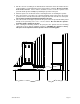
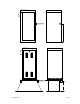
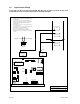
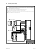
Route incoming high voltage power through conduit and into the operator up the right side of the
control box.
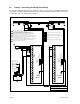
Be sure wiring is installed in accordance with local codes. Be sure to color code all wiring.
It is recommended that a surge suppresser be installed on the high voltage power lines to help
protect the operator and circuit board from surges and power fluctuations.
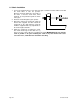
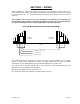
DETAIL A
DETAIL A
L1 L2 L5L4L3
GROUND
115 VAC
OUTPUT
HIGH VOLTAGE
INPUT
POWER TERMINALS
115 VAC SINGLE PHASE L1 - L2
230 VAC SINGLE PHASE L1 - L2
208 VAC THREE PHASE L1 - L2 - L3
230 VAC THREE PHASE L1 - L2 - L3
INCOMING
POWER WIRES
L1 = HOT (BLACK)
L2 = NEUTRAL (WHITE)
Page 26 9210-065-H-8-08