
Owner`s manual

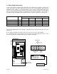
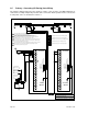

2.3 Loop Detector Wiring
Loops and loop detectors must be installed with this gate operator to prevent the gate from
accidentally closing on vehicles that may be in the path of the gate.
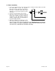
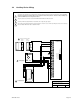
Detail A
TB 1
From inside
Reverse loop
From outside
Reverse loop
Reverse
Reverse
Exit
DOORKING, INC., INGLEWOOD, CA 90301
Title:
Date: Rev.Dwg. No.
DoorKing
Loop Detector
DoorKing
Loop Detector
Π Loops and loop detectors MUST be installed with this gate
operator to help prevent the gate from accidentally closing on
vehicular traffic.
Π Loop detector wiring is shown for DoorKing plug-in loop
detectors only. If other loop detectors are used, refer to the
installation instructions supplied with those detectors for
wiring instructions.
Π If other detectors are used, use a separate power supply to
power these detectors.
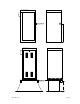
Π Loop layout shown is for a typical slide gate application with
two-way traffic, or one-way exit only traffic.
Π Reverse loops are wired in series. See detail A.
Π Refer to the Loop Information Manual (available from
www.dkaccess.com) for more information on loops and loop
detectors.
6/09
C
4404-LOOP-1
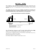
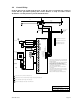
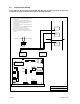
Model 9200 Series and 9500 Series Operators
Loop Detector Wiring
111 10 9 8 7 6 5 4 3 220 19 18 17 16 15 14 13 12
TIME
DELAY
REV SENS
OPEN
REV SENS
CLOSE
REVERSE
LOOP
RELAY CONTACT
REVERSING DEVICE
CONNECTOR
P5
ON
4 3 2 1 8 7 6 5 4 3 2 1
EXIT
LOOP
LIMIT SWITCH
CONNECTOR
LMT
POWER
P6
P2
P7
P8
Detail A
Page 28 9210-065-J-6-09