Owner’s Manual Series 2000 Inverter / Power Backup Systems DoorKing, Inc. 120 Glasgow Avenue Inglewood, California 90301 U.S.A. Phone: 310-645-0023 Fax: 310-641-1586 www.doorking.com P/N 2000-065 REV B, 2/01 Copyright 2001 DoorKing, Inc. All rights reserved.
Use this manual with the following models only. Model 2000-080, 2000-081, 2000-082 with circuit board 2352-010. DoorKing, Inc. reserves the right to make changes in the products described in this manual without notice and without obligation of DoorKing, Inc. to notify any persons of any such revisions or changes. Additionally, DoorKing, Inc. makes no representations or warranties with respect to this manual. This manual is copyrighted, all rights reserved.
TABLE OF CONTENTS Section 1 - Preface Introduction.......................................................................................................................................................... 7 General Precautions ............................................................................................................................................ 8 Personal Precautions..........................................................................................................................
Section 6 – Maintenance and Trouble Shooting Monthly Maintenance............................................................................................................................................31 Trouble Shooting Guide ........................................................................................................................................31 Wiring Diagram.................................................................................................................................
INTRODUCTION What is the Model 2000 Inverter? The DKS Series of Inverter / Power Backup systems are a unique style of battery backup devices. They are designed to provide an access control system with 120 volt AC power when the primary AC supply voltage source has failed. The Model 2000 will allow the access control system to maintain normal operation for an extended period of time. Most vehicular gate operator battery backup systems are designed to provide a one time open function for the gate operator.
GENERAL PRECAUTIONS This manual contains important safety and operating instructions and specifications for all models of the DKS Inverter / Backup Power Systems. This manual is the property of the owner of the equipment and must be left in their possession after the installation of the product is complete.
PERSONAL PRECAUTIONS • Someone should be within range of your voice to come to your aid when you work near batteries. • Have plenty of fresh water and soap nearby in case battery acid contacts skin, clothing, or eyes. • Wear complete eye protection and clothing protection. Avoid touching eyes while working near batteries. Wash hands when done. • If battery acid contacts skin or clothing, wash immediately with soap and water.
BATTERIES Batteries come in different sizes, types, amp hours, voltages and chemistries. Standard automobile batteries, called starting batteries, are designed to provide high starting current for short periods of time. These batteries will quickly drain under continuous loads and their life span is greatly reduced when the battery is discharged on a repetitive cycle. Deep cycle batteries are designed to handle continuous or repetitive loads for an extended period of time.
SIZING THE SYSTEM The loads on the backup power system are seldom constant. Typically, large loads are operated for only short periods of time, such as when a gate operator motor first starts. The Model 2000 has circuitry that allows the system to operate at power levels that exceed the continuous power rating of the inverter for these short periods.
SECTION 2 – INVERTER OPERATION Shown below are the controls and indicator lights on the front panel of the inverter/charger. These control and provide information when the system is in either inverter or battery charging mode of operation. NOTE: ALL SETTINGS ON THE INVERTER CONTROL PANEL HAVE BEEN PRESET AT THE FACTORY. DO NOT CHANGE THEM. The information provided in sections 1.1.1 through 1.1.10 is for reference only. 2.
2.1.3 Search Mode Watts This control is used for adjusting the sensitivity of the search mode circuit. Since the Model 2000 Power Backup System is being used as an Uninterruptible Power Supply (UPS), the search mode function should be defeated by turning the control completely to the left (counter clockwise). Protection Circuitry The inverter will automatically restart itself from the following overload conditions: low battery, high battery, shorted output, over current and over temperature.
2.1.6 Charger LED The battery charger in this inverter charges the batteries in three stages - BULK, ABSORPTION and FLOAT - to provide rapid and complete charge cycles without undue battery gassing. Stage One - Constant Current (Bulk Charge) This stage is initiated when AC is applied to the AC input of the inverter, and is terminated when the batteries reach the BULK CHARGE VOLTAGE. During this stage, the charger LED glows STEADY ORANGE.
2.1.9 Over Discharge Protection The over discharge protection control enables or disables the over discharge protection system (ODP) and allows adjustment of the AC transfer voltage. The purpose of the ODP system is to protect the batteries from being over-discharged. The over discharge protection control is turned clockwise to activate the circuit. It is defeated by turning the control fully counterclockwise.
SECTION 3 – INSTALLATION WARNING!! DO NOT CONNECT BATTERIES TO THE BACKUP POWER SYSTEM UNTIL INSTALLATION AND WIRING OF THE SYSTEM IS COMPLETE. THE BATTERIES WILL BE THE LAST COMPONENT TO BE CONNECTED PRIOR TO POWERING THE SYSTEM FOR THE FIRST TIME. Front Side Control Board Inverter 41.25 Battery Compartment 16.
3.1 LOCATION Prior to installing the backup power system, careful thought must be given as to where the unit will be installed. The system operates best when it can be installed as physically close as possible to the equipment that it is intended to operate during power outages. This reduces line loss. The backup power system also acts as a power distribution panel.
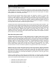
3.1.1 In this layout, the Model 2000 is installed close to the vehicular gate system. Note that incoming AC power is routed into the Model 2000, and is then distributed to the various devices to be powered. With this type of layout, it is critical that the AC wires that provide power to the Model 2000 must be of a sufficient size to handle the power required by ALL the operators powered from the Model 2000.
3.1.2 In this layout, the Model 2000 has been positioned close to the AC power distribution panel rather than being installed at the gate site. AC power is routed into the Model 2000 from the distribution panel and is then distributed to the various devices to be powered. It is critical that the AC wires that provide power to the Model 2000 be of a sufficient size to handle the power required by ALL the operators powered from the Model 2000.
3.2 MOUNTING 3.2.1 Conduits All wiring into and out of the backup power system enters the unit through the concrete mounting pad and is routed up behind the battery compartment into the circuit breaker panels. Conduits should be located so that they are in a straight line running along the back of the unit. However, there is 3.5 inches of clearance from the bottom of the battery shelf to the top of the mounting pad. Conduits can be stubbed up into this space, and then the wires can be routed as needed.
3.2.3 MOUNTING THE UNIT These steps require two people to perform them. The Backup Power Unit is heavy and will require lifting. Attempting to lift this unit by yourself can result in serious injury. A hammer drill will be required in these steps to drill the mounting holes in the concrete pad for the sleeve anchors. Mounting of the Backup Power Unit to the concrete pad requires five (5) 3/8 x 3 sleeve anchors, which are not supplied with the unit. 1. Remove the shipping carton from the Backup Power Unit.
SECTION 4 – WIRING WIRING OF THE MODEL 2000 INVERTER / POWER BACKUP SYSTEM SHOULD BE PERFORMED BY A QUALIFIED, LICENSED ELECTRICIAN. CONSULT LOCAL CODE FOR PROPER WIRE SIZE, CONNECTORS AND CONDUIT REQUIRMENTS. The Model 2000 is protected with a 30 Amp circuit breaker on the AC input power line. Each of the six branch circuits is protected with a 20 Amp circuit breaker.
4.1 AC INPUT WIRING Be sure that the AC source power is disconnected or shut-off before attempting to connect the AC input wiring to the Backup Power System. Since the Backup Power System acts as a distribution panel, the AC input wiring must be sized large enough to power the load(s) connected to the Backup Power System. Under no circumstances should the AC input wiring be sized less than 10 AWG.
4.2 AC OUTPUT WIRING The Backup Power System provides six (6) output circuits, each of which is protected by a 20-amp circuit breaker. When using this system to provide backup power for vehicular gate operators, each gate operator should be connected to its own circuit breaker. In this manner, the system will provide power for up to six (6) gate operators. The access control system (telephone entry, card readers, etc.
4.3 BATTERY WIRING WARNING!! THE INVERTER IN THIS BACKUP POWER SYSTEM IS NOT REVERSE-POLARITY PROTECTED!! If the positive terminal of the battery is connected to the negative terminal of the inverter and vice versa, the probable result is failure of every power FET in the inverter. To compound your misfortune, this type of failure is very obvious AND IS NOT COVERED UNDER THE WARRANTY. Pay close attention and double check when making the battery connections.
SECTION 5 – CONTROLS AND ADJUSTMENTS The inverter / charger has its own control panel and indicator lights. These control and provide information when the system is in either inverter or battery charging mode. NOTE: All settings on the inverter control panel have been preset at the factory – do not change them. The information below is provided for reference only.
5.1 CONTROL BOARD The Backup Power System uses a battery control board that monitors the charge condition of the battery bank. This control board will command each of the gate operators connected to the system to open sequentially thirty (30) seconds apart when the batteries reach a critical level and can no longer maintain system operation. This assures that the vehicular gates will not remain in a closed position if the battery power is depleted. 5.1.
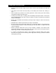
5.1.4 CONTROL BOARD WIRING Terminals P1, P2 and P3 are factory wired. The relay contacts on terminals P4, 1-14 are factory set for Normally Open (N.O.) operation. If Normally Closed (N.C.) relay contacts are required, move the contact jumper for the desired relay from the N.O. pins to the N.C. pins. Connect the respective control relay contacts to the open input on the gate operators to be backed up by this system. Use 18 AWG (minimum) wire for control relay connections.
5.1.5 OPERATION TEST BEFORE TESTING THE BACKUP POWER SYSTEM, BE SURE THAT ALL WIRING IS COMPLETE AND THAT THE BATTERIES ARE PROPERLY CONNECTED AND FULLY CHARGED. 1. Place the main AC input circuit breaker to the ON position. Place each of the branch circuit breakers that are being used to the ON position. 2. Operate the access system to assure that all components of the system function normally from the AC power source. 3.
SECTION 6 – MAINTENANCE AND TROUBLE SHOOTING MONTHLY MAINTENANCE At the minimum, check the level of the electrolyte in each battery cell once a month after the batteries have been charged, not before. It should be about ½-inch above the top of the plates, but not completely full. Most batteries have a plastic cup, which the electrolyte should just touch when full. Don’t overfill the batteries or the electrolyte will spill out of the batteries during charging.
TROUBLE INDICATION POSSIBLE CAUSE POSSIBLE SOLUTION OVERLOAD – GREEN (LED): • Comes on after the inverter was running loads. Excessive load on the AC output. Remove excessive AC loads and restart the inverter. • Comes on with the inverter off. Indicates that an AC source was wired directly to the AC output. Check for proper AC input and output wiring. • Comes on after flickering 5-10 seconds of loud humming when the AC source is connected to the inverter.
WIRE DIAGRAM 33
6.1 RMS VALUES, METERS and MEASUREMENT RMS, or Root Mean Square, is the measurement used for any time varying signal’s effective value: it is not an “Average” voltage and its mathematical relationship to peak voltage varies depending on the type of waveform. By definition, RMS Value, also called the effective or heating value of AC, is equivalent to a DC voltage that would provide the same amount of heat generation in a resistor as the AC voltage would applied to the same resistor.
6.2 BATTERY CABLE INDUCTANCE What is Inductance? When current passes through a conductor a magnetic field is set up around the conductor. As this magnetic field builds, it induces voltage in any conductor that is close by, and it induces voltage in the original conductor. The voltage induced in the original conductor is called self-inductance, and tends to oppose the current that produced it. The magnitude of the self-induced voltage is proportional to the size of the loop formed by a wire.
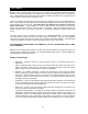
6.3 GROUNDING vs. LIGHTNING If an electrical system has components grounded at different points in the earth (detail A), large voltage differences will exist between these grounds during a lightning strike. If this voltage appears between the AC and DC side of the inverter, it could fail. Likewise, if this voltage appears between the different components of an access control system, the components can fail.
LIMITED WARRANTY DoorKing Inc. (DoorKing) warrants the Model 2000 Inverter / Power Backup System to be free from defects in material and workmanship under normal use and service for a period of two-years after the date of purchase by the original customer.
LIFE SUPPORT POLICY As a general policy, DoorKing, Inc. does not recommend the use of the Model 2000 Inverter / Power Backup System in life support applications where failure or malfunction of the DoorKing product can be reasonably expected to cause failure of the life support device or to significantly affect its safety or effectiveness. DoorKing, Inc. does not recommend the use of any of its products in direct patient care. DoorKing, Inc. will not knowingly sell its products for use in such applications.