
Operation and maintenance manual


Safety
1-69
DX140R/DX140LCR
Feet
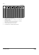
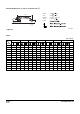
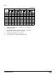
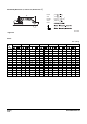
1. Load point is the end of the arm.
2. Capacities marked with an aster
i
sk (*) are limited by
hydraulic capacities.
3. Lift capacities shown do not exceed 75% of minimum
tipp
ing loads or 87% of hydraulic capacities.
4. The least stable position is over the side.
5. Lift capacities are in compliance with ISO 10567.
Unit: 1,000 Ib
A (ft)
10 15 20 Max. Reach
B (ft)
Reach
25 6.51 * 6.51 * 5.03 * 5.03 * 11.13
20 6.65 * 6.65 * 3.74 * 3.74 * 17.50
15 7.62 * 7.62 * 8.10 * 7.8 5.30 * 4.63 3.42 * 3.42 * 20.86
10 13.99 * 13.99 * 10.06 * 7.41 7.4 4.53 3.44 * 3.44 * 22.62
5 19.94 * 12.94 11.56 6.91 7.2 4.34 3.71 * 3.33 23.18
0 16.52 * 12.25 11.14 6.54 7.02 4.18 4.30 * 3.41 22.62
-5 20.68 * 12.2 10.99 6.42 6.97 4.14 5.49 * 3.89 20.84
-10 17.12 * 12.48 11.13 6.54 8.48 * 5.23 17.47