
Operation and maintenance manual


Operating Controls
2-1
DX140R/DX140LCR
2Operating Controls
The "Operating Controls" section presented here consists of the
following groups:
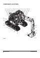
1. "Component Locations" on page 2-2
2. "Operator's Area" on page 2-4
3. "Operational Controls and Panels" on page 2-6
4. "Instrument Panel" on page 2-19
5. "Multifunction Gauge and Gr
aph
ic Information" on
page 2-25
6. "Mode Selector Buttons" on page 2-31
7. "Setting Main Menu" on page 2-33
8. "Heater and Air Conditioner Control Panel" on page 2-48
9. "Stereo" on page 2-53
10. "Miscellaneous Electrical Devices" on page 2-54
11. "Seat Adjustment" on page 2-56
12. "Ceiling Cover" on page 2-60
13. "Front Windows" on page 2-61
14. "Door Side Latch" on page 2-63
15. "Cabin Storage Compartments" on page 2-64
16. "Ashtray" on page 2-64
17. "Sun Visor" on page 2-65
18. "Hanger" on page 2-65
19. "Cup Holder" on page 2-65
20. "Emergency Glass Breaking Tool" on page 2-66
21. "Miscellaneous Access Covers and Doors" on page 2-67
Each group is explained with a point location drawing or photo
and
a bri
ef description of each control, switch, gauge or valve.
Indicator lights work besides the gauges on the instrument
panel. Th
e operator should monitor machine pressure on the
instrument panel with indicator lights. These lights will only show
there is a problem.
WARNING
AVOID DEATH OR SERIOUS INJURY
Warning lights. When any one or more
of the warning lights
on the control console, comes "ON", immediately stop
operation and stop unit. Investigate and correct the
problem before proceeding with operation.