
Service manual


G424F(FE) Service Manual Chapter 3. Engine Mechanical System 98
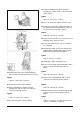
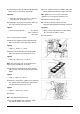
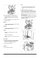
16. Second and third connecting rod bearing
attaching bolts, with a 14-mm socket wrench,
extension and handle; remove the connecting
rod caps.
17. Install tool T-9806661 in the connecting rod and
remove the piston.
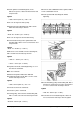
Measure
• Clearance between pistons and cylinders, which
should be 0.010 – 0.030 mm.
Important
• The pistons are available in standard size and
0.50-mm (0.020 in.) oversize.
Inspect
• Pistons for cracked walls, grooves, skirts or
supports.
• Waving in the rings fitting.
• Warping, damages or corroded areas in piston
head.
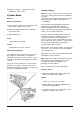
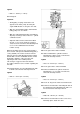
Disassemble
1. Piston pin, placing the piston in the support base
J-8606014 and using puller T-9806680-1 with
universal handle M-840911A and press.
2. Connecting rod in the piston.
Assemble
1. Connecting rod in the piston.
Clean
• The piston varnish; clean the grooves with a
proper scraper; unclog the oil grooves and
holes.
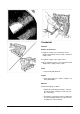
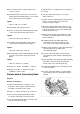
2. Piston pin; for this, proceed as follows:
Warm the connecting rod from 280° C to 320° C,
in the piston pin hole area. The heating should be
made preferably in oil bath. Cool the pin with dry
ice.
Attach the warmed connecting rod in the vise, this
with aluminum jaws.
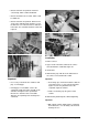
By keeping the piston touching the connecting rod
face, on the side where the pin is to be assembled,
insert it into its lodgment with the aid of tool T-
806680/20, and guide.