
Service manual


G424F(FE) Service Manual Chapter 5. Engine Management System (EMS) 121
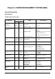
Chapter 5. ENGINE MANAGEMENT SYSTEM (EMS)
General Information
Specifications
SECM and Sensor/Switch Inputs
Q’ty
Components
G424FE G424F
Items Specifications
Environmental /
Electrical
Specifications
None None
Ambient Operating
Temperature
Operating Voltage
-20 °F to 221°F [-29 °C to 105 °C]
8-16 Vdc
Engine Control Module
(SECM 48)
1 1
Operating Temperature
Operating Voltage
Operating Environment
-20 °F to 221°F [-29 °C to 105 °C]
8-16 Vdc
SECM microprocessor may reset at
voltages below 6.3 Vdc
On-engine mounting, underhood
automotive
Camshaft Position
Sensor
0 (LP)
1 (Dual
Fuel)
None
Type
Output Voltage
Hall effect sensor
0 – 5 Volts
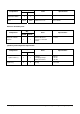
Crankshaft Position
Sensor
1 1
Type
Tooth wheel
VR sensor
58X
TMAP Sensor
1 1
MAP sensor
Intake Air Temp Sensor
Piezo- Resistivity type
0-5V output
Thermistor type
(built in MAP sensor)
2.0-3.0kohms at 20°C
LP Fuel Temperature
Sensor 1 None
Type
Resistance
Thermister
2.5kΩ@20℃
243Ω@90℃
Oxygen Sensor
2 None
Type
Output Voltage
Zirconia Sensor (Heated)
0 - 1V
Coolant Temperature
Sensor
1 1
Type
Resistance
Thermistor Type
1.0-4.0 kohms at 20°C
Acceleration Pedal
Angle Sensor
1 1
Type
APP1(Low idle)
APP2(Low idle)
APP1(Hi idle)
APP2(Hi idle)
Hall IC
0.4 ± 0.1 V
4.5 ±0.1 V
3.6 ±0.15 V
1.39 ± 0.15 V
Engine Oil Pressure
Switch
1 1
Actuation Pressure 0.3 +/- 0.1 kgf/cm^2