
Service manual


G424F(FE) Service Manual Chapter 5. Engine Management System (EMS) 137
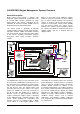
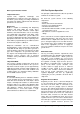
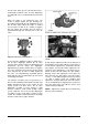
Figure 6. Parts View of N-2007 Regulator
Because vapor propane has now left the expansion
chamber, the pressure in the chamber will drop,
causing the primary diaphragm spring force to re-
open the primary valve allowing liquid propane to
enter the regulator, and the entire process starts
again. This creates a balanced condition between
the primary and secondary chambers allowing for a
constant flow of fuel to the mixer as long as the
demand from the engine is present. The fuel flow is
maintained at a constant output pressure, due to the
calibrated secondary spring. The amount of fuel
flowing will vary depending on how far the
secondary valve opens in response to the negative
pressure signal generated by the air/fuel mixer. The
strength of that negative pressure signal developed
by the mixer is directly related to the amount of air
flowing through the mixer into the engine. With this
process, the larger the quantity of air flowing into the
engine, the larger the amount of fuel flowing to the
mixer.
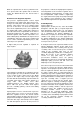
CA100 Mixer
The mixer is installed above the throttle body and
meters gaseous fuel into the airstream at a rate that
is proportional to the volumetric flow rate of air. The
ratio between volumetric airflow and volumetric fuel
flow is controlled by the shaping of the mixer fuel
cone and biased by the controllable fuel supply
pressure delivered by the pressure regulator. Fuel
flow must be metered accurately over the full range
of airflows. Pressure drop across the mixer air valve
must be minimized to assure maximum power
output from the engine.
The mixer fuel inlet is fitted with a thermistor-type
temperature sensor. This permits the SECM to
correct fuel pressure to compensate for variations in
fuel temperature. Left uncorrected, fuel temperature
variations can cause significant variations in air fuel
ratio.
A higher flow mixer is required on larger engines. A
lower flow mixer is required on smaller engines.
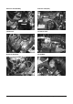
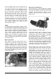
Figure 7. CA100 Mixer
CA100 Mixer Operation
Vapor propane fuel is supplied to the CA100 mixer
by the N-2007 pressure regulator/converter. The
mixer uses a diaphragm type air valve assembly to
operate a gas-metering valve inside the mixer. The
gas-metering valve is normally closed, requiring a
negative pressure (vacuum) signal from a cranking
or running engine to open. This is the third of the
three safety locks in the MI-07 system. If the engine
stops or is turned off, the air valve assembly closes
the gas-metering valve, stopping fuel flow past the
mixer. The gas-metering valve controls the amount
of fuel to be mixed with the incoming air at the
proper ratio. The air/fuel mixture then travels past
the throttle, through the intake manifold and into the
engine cylinders where it is compressed, ignited and
burned.
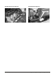
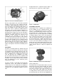
Figure 8. CA100 Mixer Attached to Throttle Body
(Refer to Figure 98.)
The air/fuel mixer is mounted in the intake air stream
between the air cleaner and the throttle. The design
of the main body incorporates a cylindrical bore or
mixer bore, fuel inlet (1) and a gas discharge jet (2).
In the center of the main body is the air valve
assembly, which is made up of the air valve (3), the
gas-metering valve (4), and air valve diaphragm (5)