
Specifications


Vehicle System System Operation 34
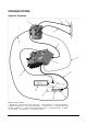
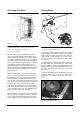
The flow divider provides continual flow of 0.8 GPM
through the brake spool to “P” port (4) of power master
cylinder. When the brake pedal is not pushed (neutral
position), the fluid goes through the flow passage (2)
between the master piston (1) and servo piston (6), flow
passage (5) and chamber (8), then returns to tank, as
shown in Fig 1.
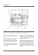
When the brake pedal is pushed, the master piston (1)
advances toward the servo piston (6). Oil flowing
through oil passage (2) is restricted and increases
pressure in chamber (3) which pushes the servo piston
more to the right. The master and servo pistons
continue to move independently in reaction to the flow
and pressure changes until a balance is reached where
the force in chamber (3) equals the force working
against servo piston in chamber (10) plus the reaction
force of spring (15) and flow passage (2) is closed (ref:
Fig 3 & Fig 4). Pressure then builds up to assist in brake
application. The operator feels the feed-back force as
pressure increases in chamber (3).
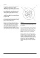
When the brake pedal is released, return spring (15)
forces master piston (1) and a servo piston (6) to return
to the initial position (or neutral position). As these
pistons return, displaced oil within chamber (10) is
replenished through check valve (11) from reservoir
(14). When the pistons have moved past the
replenishing orifice (9), pressure in chamber (10) drops
to zero and oil from reservoir (14) can now pass through
the orifice.
Relief valve (7) is built into the power master
cylinder to prevent exceeding 40 bar (580 PSI)
pressure within chamber (3). As pressure builds,
the sleeve of the relief valve shifts and
compresses the spring. This opens boost
chamber (3) to drain chamber (8) preventing
over-pressurizing the system. This limits
excessive reaction force of the brake pedal.
In case of accidental engine shut down the
system becomes mechanically operated. With no
hydraulic boost the result is greater brake pedal
force is required to stop the truck.
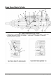
Fig 4: Detail - Boost Not Applied (2 -> 6)