TEST & ADJUSTING DX Model 2007. 7.
Index 1. Power/ Standard mode. 2. Working mode. (Digging/Trenching mode) 3. Pilot pressure. 4. Nega con (Negative Control) pressure. 5. Main relief pressure & pressure up. 6. PA/PT signal. 7. Auto speed signal. 8. Travel motor pressure. 9. Swing pressure. 10. One/ Two way signal. 11. Flow control. 12. Cooling fan RPM.
1.
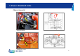
1. Power / Standard mode Test Condition : Over 50 ℃ of hydraulic oil temp, Engine max speed. Procedure 1) Select Power Mode ,Standard mode and Low engine RPM. 2) Measure power shift current and pressure value. 3) Briefly operate boom up or arm dump, observe the pressure and current again. 4) Select auto idling, low RPM, auxiliary mode. 5) Measure and record the power shift pressure and current. 1. 2.
1. Power / Standard mode 3.
2.
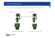
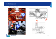
2. Working mode (Digging/Trenching mode) 1. 2. Test Condition : Over 50 ℃ of hydraulic oil temp. Procedure 1) Start the engine. 2) With Trenching mode selected, doing swing operation or not ,observe the pressure on gauge. 3) At Digging mode (Trenching mode switch off) , observe the pressure on gauge.
2. Working mode (Digging/Trenching mode) 3.
3.
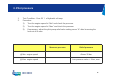
3. Pilot pressure 1. 2. Test Condition : Over 50 ℃ of hydraulic oil temp. Procedure 1) Turn the engine speed to “Min” and check the pressure. 2) Turn the engine speed to “Max” and check the pressure. 3) If necessary, adjust the pilot pump relief valve setting screw “A” after loosening the lock nut of its own. Measure pressure Relief pressure @ Min. engine speed Above 35 bar @ Max. engine speed Low pressure value + 8 bar, max.
3. Pilot pressure 3.
3.
4.
4. Negacon pressure 1. 2. Test Condition : Over 50 ℃ of hydraulic oil temp. Procedure 1) Start the engine and Min or Max engine PRM. 2) Observe and record the negacon pressure on the gauges. 3) At arm crowd or boom up full and moving operation, observe and record the nega con pressures. Condition Nega con pressure (bar) Neutral Max rpm Cyl. Moving Cyl. stall Neutral Min rpm Cyl. Moving Cyl.
4. Negacon pressure 4.
5.
5. Main relief pressure & pressure up 1. 2. Test Condition : Over 50 ℃ of hydraulic oil temp, Power up button “On”, Engine max RPM Procedure 1) At boom up stall, record the main pressure on monitor panel & the pilot pressure on the gauge installed. 2) With the pressure up button on the right joystick pressed, stall the boom cylinders and record the main pressure on monitor panel & the pilot pressure on the gauge.
5. Main relief pressure & pressure up 3. Tools : 60 bar gauge, Tee type test adapter.
5. Main relief pressure & pressure up ☞ Main Relief Valve Adjustment. 1 1. 2. 3. 4. 5. 6. 2 Loosen the upper jam nut and turn #1 clockwise till it is fully seated. Loosen the lower jam nut and adjust #2 till the “Pressure – Up value” is obtained. Set 350 bar and tighten the lower jam nut with #2 fixed. Turn out #1 till the “Main relief pressure value” is obtained. Set 330 bar and tighten the upper jam nut with #1 fixed. Recheck if both pressures are correct and if necessary, make final adjustment.
6.
6. PA/PT Signal 1. 2. Test Condition : Over 50 ℃ of hydraulic oil temp., max engine RPM. Procedure 1) Start the engine and increase the engine speed to the max. 2) Operate any of front actuators gradually while observing PA and PT. Record the values observed. 3) Operate any of travel motors gradually while doing PA and PT. Record the values. Note ) PA and PT pressures should increase sharply just before the front or travel motors begin to move.
6. PA/PT Signal 3. Tools : 60 bar gauge, Tee type test adapter.
7. Auto speed (High/ Auto speed) 1. 2. Test Condition : Over 50 ℃ of hydraulic oil temp., Auto or High Travel Speed Switch “On” . Procedure 1) Start the engine and increase the engine speed to the max. 2) Operate travel motors slowly and record the pressure on the gauge.
7. Auto speed (High/ Auto speed) 3.
8. Travel motor pressure 1. 2. Test Condition : Over 50 ℃ of hydraulic oil temp., Traveling stall Procedure 1) Fix the position of machine by pin or pushing the bucket teeth into the ground to make a travel stall condition. 2) Operate travel motors smoothly forward and reverse and record the pressure on the gauge.
8. Travel motor pressure 3. Tools : 600 bar gauge, Straight type test adapter. Big diameter pin.
9. Swing pressure 1. 2. Test Condition : Over 50 ℃ of hydraulic oil temp., Swing stall Procedure 1) Fix the position of upper structure by pushing the bucket teeth into the ground to make a swing stall condition. 2) Operate swing motors smoothly left and right and record the pressure on the gauge.
9. Swing pressure 3.
10. One / two way signal ① 1. 2. ② Test Condition : Over 50℃ of hydraulic oil temp, Breaker or shear selection switch “On”, max engine RPM. Procedure : Check pressure and energized solenoid when breaker or shear selection switch is selected.
10. One / two way signal 3.
11.
11. Flow control 1. 2. Test Condition : Over 50 ℃ of hydraulic oil temp., max engine RPM. Procedure 1) Start the engine and Max engine speed. 2) Adjusting flow on LCD panel, record the related negacon pressure on the gauges and current for front work (without breaker or crusher) 3) Adjusting flow on LCD panel and observe and record the related negacon pressure on the gauges and current for breaker or crusher.
11. Flow control 3.
12.
12. Cooling fan RPM (DX420,DX480) 1. 2. Test Condition : 50 ℃ of hydraulic oil temp., max engine RPM. Procedure 1) Start the engine. 2) Disconnect proportional valve harness and Max engine speed. 3) Measuring fan speed and adjusting pressure on proportional valve.
12. Cooling fan RPM (DX420,DX480) 4. Tools : 600 bar gauge, Screw coupling, Speed meter.
13. Transmission pilot pressure - Measuring point 1. 2. Test Condition : Over 50 ℃ of hydraulic oil temp., Braking machine without parking brake. Procedure 1) Start the engine and Low engine speed AB Travel speed switch 2) Select travel speed switch Low (I,II position) or High (III position) speed. 3) Measure each port pressure.
13. Transmission pilot pressure 3.
14. Inching traveling - Measuring point 1. Test Condition : Over 50 ℃ of hydraulic oil temp., Braking machine without parking brake. 2. Procedure 1) Start the engine and Low engine speed 2) Select travel speed switch Low ( I,II position) or High (III position) speed. 3) Measure check port pressure.
14. Inching traveling 4.
15. Cycle times – Cylinder speed Checking speed for bucket & arm Checking speed for boom 1. Objective : To measure the cycle times of the boom, arm and bucket cylinder functions. 2. Preparation and test condition 1) Warm the hydraulic oil over 50℃. 2) Power Mode, Digging mode and max engine speed.
15. Cycle times – Cylinder speed 3. Procedure 1) To measure the boom cylinder cycle time, roll out arm, roll in the empty bucket and lower the boom to the ground. 2) To measure the cycle time of the arm, roll in the bucket, the arm is placed vertical and the boom is lowered so the bucket is 0.5m above the ground. 3) To measure the bucket cylinder speed, have the side place edges are vertical as shown. 4) Measure the cycle time of each front implements.
15. Cycle times – Swing speed 1. 2. Objective : To measure the time required to make three full revolutions. Preparation and test condition 1) A flat level surface where there is ample room to safely swing the machine in a full 360 degree circle. 2) Warmed machine with hydraulic oil over 50℃. 3) With the are rolled out and the bucket rolled in, hold the bucket so that the height of the bucket pin is the same height as the boom foot pin. The bucket should be empty.
15. Cycle times – Swing speed 3. Procedures 1) Set the power mode to be Power Mode and work mode, Digging. 2) Set the engine speed to the maximum. 3) Operate the swing control lever fully. After completing the first revolution begin timing the duration required to complete exactly three full additional revolutions. 4) Operate the swing control lever fully in the opposite direction in the manner described above. 5) Perform the test three times and average the results to arrive at performance data.
15. Cycle times – Travel speed 1. 2. Objective : To measure the track operation speed with the track raised off the ground. Preparation and test condition 1) On the track to be measured, mark one shoe with chalk or paint. 2) Equally adjusted track tension. 3) Warmed machine with hydraulic oil over 50℃. 4) Swing the upper structure 90 degrees and lift up the machine using fronts like as figure.
15. Cycle times – Travel speed 3. Procedures 1) Set the power mode to be Power mode and work mode, Digging. 2) Set the Auto Travel switch to be “Off”. 3) Set the engine speed to the maximum. 4) Operate the travel control lever of the raised track in either full forward or reverse. After one revolution begin measuring the time required for the track to complete exactly three more revolutions. 5) Perform the procedure three times. Average the results to arrive at a performance data value.
15. Cycle times – Traveling speed 20 M 1. 2. Objective : To measure the time required for 20 meter traveling of machine. Preparation and test condition 1) Flat ground longer than 26 meters. 2) Equally adjusted track tension. 3) Warm the machine till hydraulic oil temperature is over 50℃. 4) Position the arm and bucket so that the bucket is 0.4 to 0.5 meters above the ground like as the figure.
15. Cycle times – Traveling speed 3. Procedures 1) Set the power mode to be Power Mode and work mode, Digging. 2) Set the Auto Travel Switch to be “Off”. 3) Set the engine speed to the maximum. 4) Begin traveling the machine in the “acceleration zone” making sure both travel levers are in the full stroked position. 5) Begin timing the travel when the machine just passes the start line of the 20 meter test course.
15. Cycle times – Travel deviation 1. 2. Objective : To check how far the machine deviates from straight. Preparation and test condition 1) Flat ground longer than 26 meters. 2) Equally adjusted track tension. 3) Warmed machine with hydraulic oil over 50℃. 4) Position the arm and bucket so that the bucket is 0.4 to 0.5 meters above the ground like as the figure.
15. Cycle times – Travel deviation 3. Procedures 1) Set the power mode to be Power Mode and work mode, Digging. 2) Set the Auto Travel Switch to be “Off”. 3) Set the engine speed to the maximum. 4) Begin traveling the machine in the “acceleration zone” making sure both travel levers are in the full stroked position. 5) Begin timing the travel when the machine just passes the start line of the 20 meter test course.
15. Cycle times – Cylinder creep 1. Objective : To measure cylinder creep which can be caused by oil leakage in the control valve or cylinders. 2. Preparation and test condition 1) Warm the hydraulic oil over 50℃. 2) Load the bucket fully. Boom 3. Procedure 1) Load the bucket fully with the arm rolled out, position the bucket so that the height of the bucket is equal to the boom foot pin. 2) Stop the engine and use a grease pencil or marker to make marks on the cylinder rods.
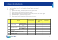
16. Checking machine condition 1. Engine Speed. Specifications (rpm) Mode No load Loaded Measured (rpm) No load Loaded Low RPM Auto Idle Standard mode Power mode 2. Relief Pressure and Negative Control (Negacon) Pressure.
16. Checking machine condition 3. Main pump pressures (Relief condition) and Negacon Pressures.
16. Checking machine condition 4. PA and PT Pressure. Front operation PA PT Travel operation PA PT Min engine speed Max engine speed 5. Work mode valve secondary pilot pressure. Work mode Swing priority solenoid valve Digging Trenching 6. Power shift valve current and pressure.
16. Checking machine condition 7. Power shift valve as per each operation Arm cd Standard Mode Power mode Boom up Travel Bucket cd Arm cd + swing Current 2nd pressure Current 2nd pressure 8. Joystick secondary pressure at boom up operation Neutral Slight operation Max operation Secondary pressure 9.
16. Checking machine condition 10. Travel motor pressure Forward Stall Pump Min engine speed Pa Reverse Stall Pb Pump Pa Pb Left motor Right motor Max engine speed Left motor Right motor 11.
16. Checking machine condition 12. Flow control proportional valve current and pressure Breaker (One line) Shear (Two way) Mode Not working Set Low flow Set High flow Full working Not working Full working Current (mA) Secondary pressure Current (mA) Secondary pressure 13. Fan speed and system pressure.