
Installation Instructions


3
Wiring
The 3525PRX/DFR/iCL contain two
separate functional modules:
The reader modules read the
contents of a compatible proximity
card and converts it to Wiegand
format.
The actuator module controls and
monitors the locking function of the
swinghandle.
These two modules operate
independently of each other and
require connection to an access
control unit (not provided), to be fully
functional.
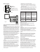
The reader modules of the swinghandle is accessed with a four pin
connector attached to a harness connected to the module’s circuit
board. The module’s connector pinout is:
Wire Color Description Note
Black GND ground
Red Positive 12 to 24VDC power supply input
Green DATA0 DATA0 output
White DATA1 DATA1 output
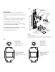
The actuator module of the swinghandle is accessed with a six pin
connector on the rear of the unit, shown below.
Wire Color Description Note
Black GND ground
Red Positive 12 to 24 VDC power supply input
Pin 3 N/C no connect
Orange Input Trigger command input (9VDC up to
supply voltage, 100 milliseconds
minimum)
Brown Electronic
Lock Status
open collector output (sink to
ground, 100mA max. load)
Blue Mechanical
Lock Status
open collector output (sink to
ground, 100mA max. load)
Input Trigger
This signal is used to control the electronic lock slide position.
For UNLOCKED position: Supply 9VDC minimum (do not exceed
supply voltage) for at least 100 milliseconds. The lock will remain
unlocked for as long as the signal is present, or a minimum of 3
seconds.
Signal timing can typically be adjusted through the access control
device.
The input trigger current draw is less than 10mA.
Electronic Lock Status Output Signal
This output will provide a 100mA MAX sink to GND when the lock slide
is electromechanically moved to the unlocked position.
Mechanical Lock Status Output Signal
This output will provide a 100mA MAX sink to GND when the handle
is in the open position or when the keylock in the actuator is manually
unlocked.
NOTE: These outputs are open collector outputs rated for input voltage
with a maximum load of 100mA. To avoid damage to the 3525PRX/
DFR/iCL, do not exceed voltage and current ratings.
Positive Red
GND Black
DATA1 White
DATA0 Green
Positive Red
GND Black
Input Trigger
Electronic Lock Status
Mechanical Lock Status
Fig. 4