B-Net® 91 04 Manual 12/2008
© Copyright by Kaba GmbH Albertistraße 3 D-78056 Villingen-Schwenningen Phone +49 7720/603-0 Fax +49 7720/603-102 info@kbs.kaba.com www.kaba.com/workforce-management All rights reserved. The document and its parts are copyrighted. Only Kaba GmbH has the right to commercialize, market and distribute this document. This document, or any part of it, may not be copied or reproduced, adapted, arranged, reworked or modified without the prior consent of Kaba GmbH.
1 About this Manual...................................................................................................................5 2 Safety Regulations..................................................................................................................6 2.1 2.2 2.3 2.4 3 Product Description................................................................................................................8 3.1 3.2 3.3 4 Technical data .....................................................
7.1.5 7.1.6 7.1.7 7.1.8 8 Description of the Subpartyline...........................................................................................42 8.1 8.2 8.3 8.4 8.5 8.6 8.7 8.8 9 RUN..................................................................................................................40 ORIGIN.............................................................................................................40 GETDGN ...............................................................................
Manual B-Net® 91 04 1 About this Manual About this Manual Validity Addressees This manual describes the Kaba B-Net 91 04 subterminal as of Serial number: 072114- 000100 Creation date: November 2008 The manual addresses specialists for mounting, installation, set-up, service, and maintenance of the device. The descriptions in this manual are intended for trained personnel. The information in this manual cannot substitute a product training.
Safety Regulations 2 2.1 Manual B-Net® 91 04 Safety Regulations Use as directed The device or system is only intended for usage as described in chapter ”Product Description”. Any use beyond the designated use is not according to rules. The manufacturer is not responsible for damages resulting from improper use. The user/operator is responsible for any risks associated with non-duly use. 2.2 General Remarks Removal of malfunctions and maintenance may only be performed by skilled technical specialists.
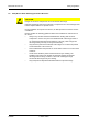
Manual B-Net® 91 04 2.4 Safety Regulations ESD (Electro Static Discharge) Protective Measures CAUTION Danger for electronic components due to electrostatic discharge. Improper handling of printed circuit boards or components can cause damages that lead to complete failures or sporadic errors. During installation and repair of the device, the ESD protective measures must be considered.
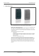
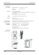
Product Description 3 Manual B-Net® 91 04 Product Description Fig. 1: Subterminal B-Net 91 04, colors anthracite and grey aluminum B-Net 91 04 is a subterminal to be used for access control. It is compatible with the terminal series Bedas / Bedanet 90 00. The reader is in a sealed plastic housing and also designed for use under rough environmental conditions. Its compact design allows for installation on door frames or similar surfaces.
Manual B-Net® 91 04 3.1 Product Description Technical data Power supply Interface • Operating voltage: 12 – 32 V DC / 16 – 27 V AC • Current consumption: max. 150 mA at 24 V • RS-485 2-wire subpartyline Protocol: BPA9; transmission parameters: 9600/19200 baud, 7 data bits, parity even, 1 stop bit Other settings via system mode are possible. Output • 1 relay output, contact load 30 V AC/DC, max. 1 A Readers • LEGIC® reader Reading and writing of LEGIC® media.
Product Description 3.2 Manual B-Net® 91 04 Conformity This device complies with the standards EN 60950-1 2003 EN 301 489-3 V1.4.1 EN 300 330-2 V1.1.
Manual B-Net® 91 04 4 4.1 Design and Function Design and Function Models / Delivery volume The device can be delivered in two versions: • With 3.5 mm connecting cable (standard) • With terminal board without connecting cable (optional) The connecting frame provides additional room for cable storage, if needed, and possesses a predefined location of rupture for cable outlet for surface mounting. The connecting frame is always part of the delivery.
Design and Function 4.2 Manual B-Net® 91 04 Input possibilities LEGIC® media, such as badges, key tags, smartkeys, etc., can be read. The LEGIC® medium is positioned in front of the subterminal. Fig. 3: Entry of LEGIC® media The reading distance depends on the environmental conditions and the type of LEGIC®. 4.3 4.3.1 • The range of a LEGIC® badge is 5 cm. • The range of a LEGIC® key tag is approx. 2.5 cm.
Manual B-Net® 91 04 4.4 4.4.1 Design and Function Operating Modes Online mode In online operation, the device works as subterminal of an access control. The device can be connected to access control units of the device families Bedas, Bedanet and B-Net, such as B-Net 92 50, Bedanet 92 90, or a time recording terminal of the B-Net series. One or several subterminals are connected to the control unit by means of the RS-485 subpartyline. The subterminal is operated in the polling mode.
Mounting and Installation 5 5.1 Manual B-Net® 91 04 Mounting and Installation Installation Conditions General Installation site An accurate installation of all components is a basic requirement for proper functioning. The following installation instructions must be adhered to. The device can be mounted either directly on the wall or on a door frame. For cable outlet, a drilling of approx. 10 mm diameter is required. An edge which might be produced must be trimmed.
Manual B-Net® 91 04 Clearances Mounting and Installation Between two B-Net 91 04 devices, a distance of 20 cm must be observed on all sides. min. 20 cm min. 20 cm min. 20 cm Fig. 5: Minimum distance between devices with LEGIC® readers. To steel parts, a distance of 10 cm must be observed on all sides. If this distance is not observed, the reading quality is impaired. Then, the maximum reading distance is not achieved. Problems may appear with different LEGIC® media.
Mounting and Installation 5.2 Manual B-Net® 91 04 Installation Diagram 1 2 5 A A 3 B 5 C 4 Fig. 6: B-Net 91 04 installation in online operation 1 Access Control Unit 2 B-Net 91 04 Power is supplied via the access control unit. The power supply is also led through the data line (A). This is permitted for cable lengths up to 20 m. The door opener is led to the access control unit. 3 Subterminal B-Net 91 04 with separate power supply (4). The door opener is connected to the subterminal.
Manual B-Net® 91 04 Mounting and Installation 2 1 C B 3 Fig.
Mounting and Installation 5.3 Manual B-Net® 91 04 Installation Lines (A) Data line to subterminal The subterminals are connected to the control unit via a 2-wire subpartyline. It can be designed in star-shape or as partyline. NOTICE! The shielding of the data line is generally connected on both sides. The complete bus connection (master lines and branch lines) may be up to 2,000 meters long. One branch line may not exceed 100 m. For short distances (up to 20 meters max.
Manual B-Net® 91 04 5.4 Mounting and Installation Mounting The device can be mounted either directly on the wall or on a door frame. The terminal frame included in the delivery must be used for mounting the device on metal surfaces. For cable outlet, a drilling of approx. 10 mm diameter is required. A possible edge must be trimmed. A screw guide is positioned in the middle of the housing’s top and bottom.
Mounting and Installation 5.5 Manual B-Net® 91 04 Installation of devices with connecting cable For the prolongation of the cable tail or for the link to an already mounted data cable, appropriate butt connectors are attached. Possible wire and/or stranded wire dimensions are AWG 26-22 (D:0,4-0,65, A:0,13-0,36) The butt connectors must be fastened offset on the cable to allow introducing the connecting position into an empty tube or through a bore hole into the door frame.
Manual B-Net® 91 04 5.7 Mounting and Installation Pin assignment The following table shows designations and assignments of clamps with regard to wire colors. Color Description Data Power Supply red AC/DC + or + Gray Ground blue AC/DC + or + 12-32 V DC or 16-27 V AC Power consumption max. 150 mA at 24 V Relay yellow Opener (NC) green Center contact (COM) orange Closer (NO) Contact loading capacity: 30 V AC/DC; 1 A max.
Mounting and Installation 5.8 5.8.1 Manual B-Net® 91 04 Description of connections Power Supply The B-Net 91 04 subterminal can either be operated at 12 V DC or 24 V AC/DC. The current consumption with 24 V is 150 mA at maximum. 5.8.2 Relay output The function of the R1 relay is defined by the access control unit in online mode. In stand-alone mode, the relay is used for the control of the door opener.
Manual B-Net® 91 04 5.9 Mounting and Installation DIP-Switch The DIP switch row is located under the lower front panel. Therefore, the switches must be adjusted before fixing the front panel. Remark All switches are set to ON when delivered. 1 2 3 4 5 6 7 8 9 10 OFF Fig. 10: DIP switch position GID/DID 12/2008 The group and device identifications (GID/DID) serve for addressing a subterminal via the RS-485 interface.
Mounting and Installation Baud Rate Manual B-Net® 91 04 The baud rate of the RS-485 subpartyline can be set by means of switch 8. The remaining transmission parameters are fix. 7 data bits, even parity, 1 stop bit, response control 3 seconds, operation monitoring 3.5 seconds Switch BPA/9 protocol 9 on off BPA/9 protocol BPA/9 protocol (standard) no protocol All DIP switches can be deactivated by means of switch 10.
Manual B-Net® 91 04 Mounting and Installation 5.10 Final assembly Fasten the front foils for finishing installation. NOTICE! Before fixing the front foils, the device must be put into service, see chapter 6. Fig. 11: Fixing the front foils NOTICE! Observe the following to avoid leaks: • Use only new front foils with undamaged peel-off foil. • The housing surfaces on which the foil is to be fixed must be dry, fat-free and clean.
Start-Up 6 Manual B-Net® 91 04 Start-Up NOTICE! The descriptions in chapter Set-up refer to devices with standard configuration preset in the factory. By default, the driver "LEGIC® prime read-only" is active. This driver is compatible to the Bedas/Bedanet series, i.e. media with previous data structure can be read. The stand-alone mode is only possible with standard configuration. Other drivers can be configured in system mode, see chapter 7.
Manual B-Net® 91 04 6.1 Start-Up Online mode Requirements • A connection to the access control unit must exist. • The DIP switches must have been set in accordance with the description in chapter 5.9. Set-up procedure 12/2008 1. Provide the subterminal with power. 2. Start up the subterminal at the control unit (see the Control Unit Manual). 3. Perform a functional test.
Start-Up 6.1 Manual B-Net® 91 04 Stand-alone operation Requirements • The connections to power supply and door opener must exist. • The DIP switches must have been set in accordance with the description in chapter 5.9. • A service PC and the parameter setting tool, order number 04036126, must be available. In the service PC, the program "List Editor" (listedit.exe) must have been installed. This program is part of the parameter setting tool. Set-up procedure 1.
Manual B-Net® 91 04 6.2 Start-Up Cold start The device can be reset to default settings by means of a cold start. How to perform a cold start: • Turn off the device • Push the cold start button and keep it pressed • Turn the device on • Release the cold start button after approx. 3 seconds After a successful cold start, an acoustic signal can be heard, and the status LED flashes three times. 1 2 Fig. 13: Cold start button (1) and status LED (2).
Start-Up 6.4 Manual B-Net® 91 04 Adjusting the reader The reader has been adjusted in the factory to an optimum range. Normally, it needs not to be readjusted. The reader range is influenced by the damping of conducting material around the reading unit (e.g. housing, built-in units, conductive paint, reinforced concrete, etc.). If used in critical environment (small distance to metal parts, etc.), the reading characteristics might be improved by an adjustment.
Manual B-Net® 91 04 7 System mode System mode The system mode allows parameter setting for the device. Remark Default parameters can be modified in system mode. However, this is only required for special applications. The "online" and "stand-alone" modes described in this manual require factory settings. Therefore, parameters have not to be changed in system mode for these operating modes. The system mode is an imitation of the operating system. It can be accessed via the data interface of the device.
System mode 7.1 Manual B-Net® 91 04 Commands Commands only contain capital letters and terminate with . When entering commands, the characters following the command are ignored, as parameters might follow if the device is provided with an operating system. A wrong command is shown as follows: Command not found >_ Once a command has been called successfully, it will be processed. Upon termination of a command, the device terminal displays a prompt.
Manual B-Net® 91 04 7.1.1 System mode SETHWC The SETHWC command (Set Hardware Configuration) is used to enter the parameters defining the hardware of device. After having changed the hardware parameters, a cold start must be performed so that the device applies the defined state. The hardware parameters are not changed by the cold start.
System mode 7.1.1.
Manual B-Net® 91 04 System mode CIR type: 2-digit type for CIR 1+2 00 No CIR 01 CIR exists Status and generation depend on component for AUX channel LEDs 2-digit number of LEDs 00 No LEDs 01 1 LED 02 2 LEDs Outputs 2-digit number of outputs 7.1.1.2 12/2008 00 no output 01 1 output Default configuration Protocol type 01 BPA/9 protocol AUX 1 16 LEGIC prime – read-only 00 No CIR Serial interface 9600 Baud, 8 data bits, no parity, 1 stop bit Number of LEDs 02 No.
System mode 7.1.2 Manual B-Net® 91 04 GETHWC The GETHWC command (Get Hardware Configuration) displays the parameters described under SETHWC.
Manual B-Net® 91 04 7.1.3 System mode GETPRG The GETPRG command (Get Program Number) requests the program number of the device.
System mode 7.1.4 Manual B-Net® 91 04 LOWPAR The LOWPAR command (Low Level Parametrierung) is used to adjust the parameters of the data interface. The parameters for a protocol are only requested if a protocol with SETHWC command has been registered. These parameters are reset to default values after a cold start.
Manual B-Net® 91 04 System mode Additional parameters with protocol type 02: Header Length Up : '00' : 00 Down : '00' : 00 >_ 7.1.4.
System mode 7.1.5 Manual B-Net® 91 04 RUN The command RUN (restart of the program) is used to quit the system mode and perform a warm start. Example: >RUN_ or >RUN,,S_ The warm start is indicated by the following message: >Restarting … 7.1.6 ORIGIN The ORIGIN command resets the device to factory settings. This applies to all cold start parameters, to hardware parameters that can be set using the SETHWC command and to the diagnostics data.
Manual B-Net® 91 04 7.1.7 System mode GETDGN The GETDGN command is used to query diagnostics data (possible errors). Query without error messages: >GETDGN_ No Errors found >_ Query with error messages: >GETDGN Errors found Code: 010 : Meaning: 01 Error while allocating memory >_ The following error codes are possible: 7.1.
Description of the Subpartyline 8 Manual B-Net® 91 04 Description of the Subpartyline In online mode, data transfer takes place via the subpartyline. The subpartyline is an RS485 bus operated in 2-wire technology. Normally, transmission takes place at 19,200 baud, parity even and one stop bit. Alternatively 9,600 baud are also possible. 7 bit ASCII characters are transmitted. 8.1 BPA Subset The BPA (Benzing Protocol Asynchronous) is a master slave protocol with the subterminal being the slave.
Manual B-Net® 91 04 8.3 Description of the Subpartyline Control Characters and Control Sequences Remark Control characters are displayed in angle brackets, e.g. ESC (1Bhex) as . An underline character “_” is used as blank (2Øhex). In the following examples “0” is used as group address (GID) and “1” as device address (DID).
Description of the Subpartyline 8.5 Manual B-Net® 91 04 Data from Subterminal to Control Unit Transmit polling Control unit Subterminal The subterminal does not respond if the address is different from its own address, or if an error has been detected, or if the two address characters are different. The control unit repeats the transmit poll after an internal time-out. GID GID DID DID no response In the case of the same address, the subterminal must respond.
Manual B-Net® 91 04 8.6 Description of the Subpartyline Data from the Control Unit to the Subterminal Receive polling Control unit Subterminal The subterminal does not respond if the address is different from its own address, or if an error has been detected, or if the two address characters are different. The control unit repeats the receive poll after an internal time-out.
Description of the Subpartyline 8.7 Manual B-Net® 91 04 Escape sequences The subterminal functions are controlled by the following escape sequences. Which ESC sequences are used or supported depends on the particular control unit. 8.7.1 Controlling LED, relay and beeper With the following sequences, the relay and the acoustic signal transmitter (beeper) in the subterminal are controlled.
Manual B-Net® 91 04 8.7.3 Description of the Subpartyline Device configuration The device configuration of the subterminal is requested by means of the following ESC sequence. The subterminal sends the ESC sequence “Device configuration” in response. Meaning Code Requesting equipment configuration [c Response from the subterminal [:2;Ps;Ps;..c The number of configuration entries may vary depending on the device configuration.
Description of the Subpartyline 8.7.5 Manual B-Net® 91 04 Recorded data After entering a badge, the subterminal will send the following sequence. Meaning Code Badge data [?11 OPDATA\ 1 2 1) Space = 20Hex 2) O as in Otto = 4FHex DATA: Badge data After pressing a key, the subterminal will send the following sequence. 8.7.6 Meaning Code Key (displayable character) 20Hex ..
Manual B-Net® 91 04 8.7.8 Description of the Subpartyline Customer number list If no entries are stored in the customer number list (factory setting), only those badges are accepted which have a segment containing SSC 02 and a fixed structure of badge data according to Kaba group header. Non-segmented badges may have an arbitrary SSC, but must also be coded according to Kaba group header. The customer number list allows to accept also badges with a different SSC and another data field structure.
Description of the Subpartyline Manual B-Net® 91 04 The following example corresponds to the setting according to Kaba group header. [?19_OP04020000000000001411250101\ The following ESC sequences allow the entries of the customer number list to be requested. Meaning Code 1. Request entry [?1c Request another entry [?2c As response, the subterminal sends the ESC sequence "Customer number list", description see above. [?19_O Paabbbbbbbbccccccddeeffgghh\ 50 ©
Manual B-Net® 91 04 8.7.9 Description of the Subpartyline Control stand-alone operation The device can also be operated as a stand-alone unit. When a simple badge or customer number check is sufficient, a simple access control can be implemented. To do this, the stand-alone mode is activated, and the respective badge or customer numbers are deposited in the customer number list. If a list entry contains 14 digits of customer and badge number, a single badge will be authorized.
Description of the Subpartyline 8.
Manual B-Net® 91 04 9 Packaging / Returns Packaging / Returns Not properly packaged components and devices can cause costs due to damages during shipping. Please note the following when dispatching Kaba products. Kaba GmbH is not liable for products that have been damaged due to negligent packaging. 9.1 Complete Devices The original packaging has been specifically designed to fit the device. It offers maximum protection against damage in transit.
Packaging / Returns 9.3 Manual B-Net® 91 04 Labeling Complete return documents and a correct labeling allow for fast processing. Please make sure that each package includes a delivery note. The delivery note should contain the following information: • Number of devices or components per package • Product numbers, serial numbers, specifications • Name and address of your company / contact person • Reason for return, e.g.
Manual B-Net® 91 04 Disposal 10 Disposal This product complies with the WEEE directive and is, according to DIN EN 50419, marked with the “Crossed out garbage can” symbol. See chapter 3.3 Labeling. The symbol refers to separated disposal of electric and electronic devices in EU countries. Please do not dispose of the device in your regular garbage. Used devices contain valuable materials that should be recycled. Used devices should therefore be disposed of via your country’s take back system.
Index Manual B-Net® 91 04 11 Index ESD (Electro Static Discharge) Protective Measures ......................................................... 7 A Access Control Unit ............................................13 Acoustic acknowledgment ..................................48 Acoustic signal generator ...................................12 G GID..................................................................... 23 Grounding ..........................................................
Manual B-Net® 91 04 Index Protection class ....................................................9 S Protocol.................................................................9 Service PC ......................................................... 13 R Stand-alone operation ................................. 13, 28 Rated reader range.............................................12 Standards........................................................... 10 Reader ..............................................