
User's Manual
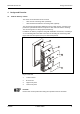
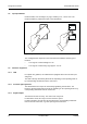
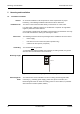
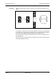
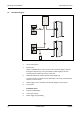
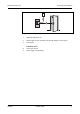
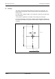
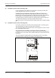
Table Of Contents
- 1 About this Manual
- 2 Safety Regulations
- 3 Product Description
- 4 Design and Function
- 5 Mounting and Installation
- 6 Start-Up
- 7 System mode
- 8 Description of the Subpartyline
- 9 Packaging / Returns
- 10 Disposal
- 11 Index

Mounting and Installation Manual B-Net® 91 04
14 © Kaba GmbH 12/2008
5 Mounting and Installation
5.1 Installation Conditions
General
An accurate installation of all components is a basic requirement for proper
functioning. The following installation instructions must be adhered to.
Installation site
The device can be mounted either directly on the wall or on a door frame.
For cable outlet, a drilling of approx. 10 mm diameter is required. An edge which
might be produced must be trimmed.
A screw guide is positioned in the middle of the housing’s top and bottom. Use only
the screws included in the delivery for fastening the device.
Connectors
The following connectors must be prearranged at the installation site of the device.
• Power supply
• Data line for access control unit (online operation only)
• Cables to the door opener (if required)
Grounding
The terminal must
be grounded!
To guarantee the highest possible noise immunity according to EMC, the ground
wire must be led to the terminal and connected.
Mounting height
140 c
m
Fig. 4: Recommended mounting height 140 cm to top edge of terminal.
Electromagnetic
fields
The terminal must not be installed in the area of strong electromagnetic fields,
caused by e.g. switching power supply, power lines, phase controllers, etc.!
Electromagnetic fields can affect the reading power or cause failures, in particular
with contact-free readers (LEGIC, Mifare).