
User's Manual
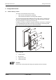
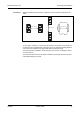
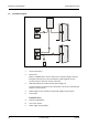
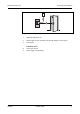
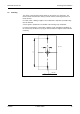
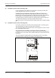
Table Of Contents
- 1 About this Manual
- 2 Safety Regulations
- 3 Product Description
- 4 Design and Function
- 5 Mounting and Installation
- 6 Start-Up
- 7 System mode
- 8 Description of the Subpartyline
- 9 Packaging / Returns
- 10 Disposal
- 11 Index

Mounting and Installation Manual B-Net® 91 04
18 © Kaba GmbH 12/2008
5.3 Installation Lines
(A) Data line to subterminal
The subterminals are connected to the control unit via a 2-wire subpartyline. It can
be designed in star-shape or as partyline.
NOTICE!
The shielding of the data line is generally connected on both sides.
The complete bus connection (master lines and branch lines) may be up to 2,000
meters long. One branch line may not exceed 100 m.
For short distances (up to 20 meters max.), it is permitted to have the operating
voltage for the subterminal and the data line in one single cable. In this case, the
subterminal is grounded via the shield of the data line.
For line lengths over 20 m, a separate power supply cable (C) must be provided for
the subterminal.
Line requirements:
Shielded line with twisted wire pairs,
cable diameter 0.4 mm to 0.6 mm
for instance standard telephone cable J-Y (St) Y 2 x 2 x 0.6 mm.
Recommended cable:
CAT.5 S-UTP 4 x 2 AWG 24 or AWG 22 (according to EIA/TIA568).
(B) Line to the door opener
Line requirements:
Cables with a cable diameter from 0.5 mm to 0.8 mm can be used.
Recommended cable:
CAT.5 S-UTP 4 x 2 AWG 24 or AWG 22 (according to EIA/TIA568) or higher.
(C) Power supply and grounding
In online operation, power is supplied by the superior control unit and can be tapped
easily from there.
If the device is used without control unit or if power cannot be supplied by the
control unit, a separate supply unit, e.g. SV 100, SV 900, SV 905, must be used.
In case of long lines, the voltage drop - caused by the line resistance - must be
considered.
The ground wire must be led from the power supply to the terminal.
Cables with a cable diameter from 0.5 mm to 0.8 mm can be used.
Three wires are required for power supply + ground (SV 100 / SV 900).
If door-opener voltage is required, two further wires are needed (SV905).