
User's Manual
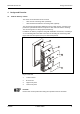
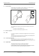
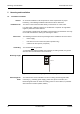
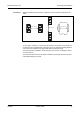
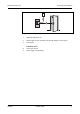
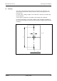
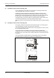
Table Of Contents
- 1 About this Manual
- 2 Safety Regulations
- 3 Product Description
- 4 Design and Function
- 5 Mounting and Installation
- 6 Start-Up
- 7 System mode
- 8 Description of the Subpartyline
- 9 Packaging / Returns
- 10 Disposal
- 11 Index

Manual B-Net® 91 04 Mounting and Installation
12/2008 © Kaba GmbH 19
5.4 Mounting
The device can be mounted either directly on the wall or on a door frame. The
terminal frame included in the delivery must be used for mounting the device on
metal surfaces.
For cable outlet, a drilling of approx. 10 mm diameter is required. A possible edge
must be trimmed.
A screw guide is positioned in the middle of the housing’s top and bottom.
In order to avoid danger of concealed or hidden cracks and tightness problems at
the screw head, this device may only be mounted with the original screws included
in delivery.
Ø
3,5
Ø 10
77
Fig. 8: Hole pattern for B-Net 91 04; dimensions in mm