
User's Manual
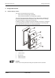
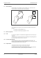
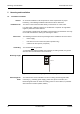
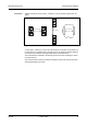
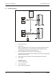
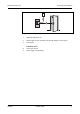
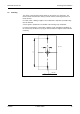
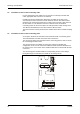
Table Of Contents
- 1 About this Manual
- 2 Safety Regulations
- 3 Product Description
- 4 Design and Function
- 5 Mounting and Installation
- 6 Start-Up
- 7 System mode
- 8 Description of the Subpartyline
- 9 Packaging / Returns
- 10 Disposal
- 11 Index

Mounting and Installation Manual B-Net® 91 04
20 © Kaba GmbH 12/2008
5.5 Installation of devices with connecting cable
For the prolongation of the cable tail or for the link to an already mounted data
cable, appropriate butt connectors are attached.
Possible wire and/or stranded wire dimensions are AWG 26-22 (D:0,4-0,65,
A:0,13-0,36) The butt connectors must be fastened offset on the cable to allow
introducing the connecting position into an empty tube or through a bore hole into
the door frame. In case the butt connectors cannot be used, the attached
connecting frame can be used as place for cable joint and/or cable storage room.
The different stranded wires in the cable tail have different colors.
The butt connectors can be joined with the stranded wires with a standard crimping
plier.
5.6 Installation of devices with connecting panel
As an option, the B-Net 91 04 terminal can be delivered with a connecting panel.
The terminal board is located on the back side of the device.
The connecting clamps can be drawn from the connecting panel in order to render
the connecting procedure easier.
The connecting panel is available as spare part. Owing to its double plug
configuration, it can even be used if the subterminal was delivered with cable tail,
for instance, if the cross section of the installed cable does not match with the butt
connectors.
The connecting panel is labeled with the corresponding seizure of the clamps.
During discharge of tensile load, the shield can be directly laid up.
A
C
B
A
C
B
~
+
~ -
~+
~ -
Fig. 9: Terminal board