
User's Manual
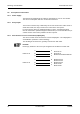
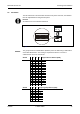
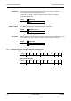
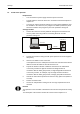
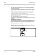
Table Of Contents
- 1 About this Manual
- 2 Safety Regulations
- 3 Product Description
- 4 Design and Function
- 5 Mounting and Installation
- 6 Start-Up
- 7 System mode
- 8 Description of the Subpartyline
- 9 Packaging / Returns
- 10 Disposal
- 11 Index

Mounting and Installation Manual B-Net® 91 04
22 © Kaba GmbH 12/2008
5.8 Description of connections
5.8.1 Power Supply
The B-Net 91 04 subterminal can either be operated at 12 V DC or 24 V AC/DC.
The current consumption with 24 V is 150 mA at maximum.
5.8.2 Relay output
The function of the R1 relay is defined by the access control unit in online mode. In
stand-alone mode, the relay is used for the control of the door opener.
For door openers, which are supplied with direct current, a freewheeling diode
must be connected in parallel to suppress interference (in reverse-bias direction). A
varistor must be connected in parallel to AC door openers.
5.8.3 Data interface to access control unit (subpartyline)
The access control unit is connected via a 2-wire subpartyline. The subpartyline is
an RS485 bus operated in 2-wire technology.
The shielding of the data line is generally connected on both sides.
NOTICE!
Please pay attention to the correct pin assignment of the different control units.
A
A
B
B
B-Net 91 04
C
C
B-Net 92 50
B-Net 93 xx
Bedanet 92 90 Rack BEX105
A
B
B
A
B-Net 91 04
C
C
Bedanet 92 20
Bedanet 92 90
Bedanet 93 60
Bedas 92 90
Bedas 93 60