
User's Manual
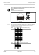
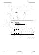
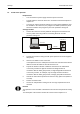
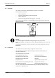
Table Of Contents
- 1 About this Manual
- 2 Safety Regulations
- 3 Product Description
- 4 Design and Function
- 5 Mounting and Installation
- 6 Start-Up
- 7 System mode
- 8 Description of the Subpartyline
- 9 Packaging / Returns
- 10 Disposal
- 11 Index

Start-Up Manual B-Net® 91 04
30 © Kaba GmbH 12/2008
6.4 Adjusting the reader
The reader has been adjusted in the factory to an optimum range. Normally, it
needs not to be readjusted.
The reader range is influenced by the damping of conducting material around the
reading unit (e.g. housing, built-in units, conductive paint, reinforced concrete,
etc.).
If used in critical environment (small distance to metal parts, etc.), the reading
characteristics might be improved by an adjustment. The reader can thus be
adapted to the installation environment to limited extent.
There is a small trimmer on the front of the device. This trimmer can be accessed
after removing the housing frame.
The adjustment should be made using an alignment pin.
An oscilloscope or LEGIC® Powermeter, order number 04032432, can be used for
adjustment.
Adjusting using an oscilloscope
The logic probe is converted into a measuring loop (connect logic probe ground to
test tip) or extend the test tip by a short piece of wire (antenna effect). The logic
probe must be fastened in front of the reader. The pulses are then set to max.
amplitude.
Adjusting using LEGIC® Powermeter
Fasten the powermeter in front of the reader. Adjust the knob on the powermeter
so that the LED field is lighted in yellow/green.
Then select maximum amplitude on the trimmer.
Fig. 14: Trimmer position for reader adjustment