
User's Manual
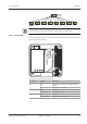

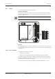
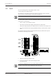


Table Of Contents
- Table of Contents
- 1 About this Document
- 2 Grouped safety messages
- 3 Product Description
- 4 Design and function
- 4.1 Opening the housing
- 4.2 Functional principle
- 4.3 Access control with B-Client AC30
- 4.3.1 Operating states
- 4.3.2 Sequence of authorization checks
- 4.3.3 Examples of door surveillance time sequences
- 4.3.3.1 Normal sequence with pass through control
- 4.3.3.2 Door is not opened after release (extended access control)
- 4.3.3.3 No pass through (extended access control)
- 4.3.3.4 Door breakup (door monitored in basic state)
- 4.3.3.5 Door open too long
- 4.3.3.6 Time exceeded access with door handle
- 4.3.3.7 Bolt monitoring, normal sequence
- 4.3.3.8 Bolt monitoring, bolt message without door release
- 4.3.3.9 Bolt monitoring, bolt position time exceeded when locking
- 4.3.3.10 Bolt monitoring, bolt position time exceeded when unlocking
- 4.3.3.11 Bolt monitoring, bolt position time exceeded when locking – after door has not been opened
- 4.3.3.12 Normal sequence with motor-driven door
- 4.4 Light emitting diodes
- 5 Installation
- 5.1 Installation conditions
- 5.2 Installation diagram
- 5.3 Installation lines
- 5.4 Wall mounting
- 5.5 Cable routing
- 5.6 Setting the PoE switches
- 5.7 Connections
- 5.7.1 Network connection
- 5.7.2 Overview of terminals
- 5.7.3 External 24 V DC power supply
- 5.7.4 Registration units
- 5.7.5 Readers via RS-485
- 5.7.6 Readers via Wiegand
- 5.7.7 Inputs
- 5.7.8 Outputs
- 5.7.9 Standard assignment of inputs/outputs (B-Client AC30)
- 5.7.10 Configuration-dependent assignment (B-Client AC30)
- 5.7.10.1 Configuration 0: Subterminal without access
- 5.7.10.2 Configuration 1: Door with 2 door opener keys
- 5.7.10.3 Configuration 2: Door with 1 subterminal and 1 door opener key
- 5.7.10.4 Configuration 3: Door with 2 subterminals and contact mat, barrier, etc.
- 5.7.10.5 Configuration 4: Sally port with 2 subterminals and 2 door opener keys
- 5.8 Vandal contact
- 5.9 Fastening the cover
- 6 Start-up
- 7 Packaging/Return
- 8 Disposal
- 9 Appendix
- Index

Technical Manual Installation
5704045376 - 05/2016Kaba access manager 92 30
5.7.8 Outputs
The access manager has 3 relay outputs OUT1 to OUT3.
Contact rating: 30 V AC/DC; 2 A max.
The outputs can be used for the activation of motor locks, door openers, turnstile
drives, technical alarm day/night, security alarm day/night etc.
The function of the individual outputs depends on the settings of the terminal soft-
ware.
The wiring of the output OUT1 can be adjusted via jumper (1). The following variants
are possible as an alternative:
• OUT1 is used as a potential-free contact
• The internal 12 V DC power supply is switched to the output OUT1.
• A DC power supply applied to the VREL terminal is switched to the output OUT1.
• The external 24 V DC power supply (24 V EXT terminal) is switched to the output
OUT1.
The outputs OUT2 and OUT3 are designed permanently as potential-free relay out-
puts with one switching contact each.
1 Jumper for the wiring of output OUT1
2 Fuse F1 for protection of the power supply via OUT1
Fuse value: T2.5 A
The fuse is plugged in and can be replaced without problems.
The fuse F1 may only be replaced with fuses of the same type.