
Instruction manual


16
POWER SUPPLY BOARD
+L -L +R -R +L -L +R -R
DS1
DS2
DS3
DS4
R18
VR49 VR48 VR44 VR46 VR14 VR13
RL
DS1
DS2
DS3
DS4
R18
VR49 VR48 VR44 VR46 VR14 VR13
RL
2 SIGNAL BOARDS
2 LED DRIVER BOARDS
- 25 dB (A)
- 36 dB (B)
+5 dB (A)
-6 dB (B)
-11 dB (B)
0 dB (A)
+14 dB (A)
+3 dB (B)
+5 dB (A)
-6 dB (B)
-11 dB (B)
0 dB (A)
VR49 VR48 VR44 VR46 VR14 VR13
RL
VR49 VR48 VR44 VR46 VR14 VR13
RL
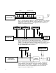
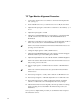
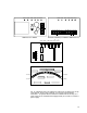
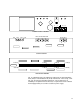
Fig. 17. Simplified view of key alignment components on Model 12-A (12-B)
circuit boards. Refer to Fig. 5 and Fig. 6 for specific panel mounting
instructions. Check with the factory on availabilty of an optional Interface
Board (as a replacement for the standard Power Supply Board) for use with
a customer's power supply.