THE INSTALLERS / INTEGRATORS DREAM ENCLOSURE PRODUCT INSTRUCTIONS D2 ENCLOSURE SERIES 1
THE INSTALLERS / INTEGRATORS DREAM ENCLOSURE Table of Contents Limited Warranty Info .................................................................................................................................................................................... 1 Product Installation Precautions and Warnings .............................................................................................................................................. 2 D2 Component Checklist for camera installation .....
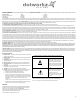
LIMITED WARRANTY FOR DOTWORKZ SYSTEMS INC. PRODUCTS DOTWORKZ SYSTEMS INC. warrants this Product to be free from defects in material or workmanship, as follows: PRODUCT CATEGORY PARTS LABOR All Enclosures and Electronics One (1) Year One (1) Year Power Supplies One (1) Year One (1) Year Accessory Brackets One (1) Year One (1) Year During the labor warranty period, to repair the Product, Purchaser will either return the defective product; freight prepaid, or deliver it to Dotworkz Systems Inc.
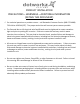
PRODUCT INSTALLATION PRECAUTIONS – WARNINGS – ADDITIONAL INFORMATION (RETAIN THIS DOCUMENT) 9 For technical questions or product returns – call Dotworkz Customer Service (866‐575‐4689) 7:30 AM to 4:30 PM (PST). The proper technician will contact you as soon as possible. The External Nut on All electrical wire feed Glands must be tightened to create a weather tight seal prior to putting D2 in service. Failure to create this seal may result in water incursion into enclosure.
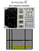
D2 Component Checklist 5 4 6 9 10 11 12 7 8 13 3 2 1 14 15 16 17 Number QTY Description Type 1 2 3 4 5 6 7 8 9 10 11 12 13 14 15 16 17 Next Page Aluminum Aluminum Aluminum Aluminum Aluminum Stainless Steel Stainless Steel Stainless Steel Stainless Steel Stainless Steel Stainless Steel Stainless Steel Stainless Steel Aluminum Stainless Steel Aluminum Stainless Steel Aluminum 1 4 4 4 4 2 1 1 2 2 2 4 4 4 4 4 4 1 Camera Bracket Mount Plate .5" Standoffs (8‐32) .75" Standoffs (8‐32) 1.
D2 Component Checklist Axis 231D/232D Special Camera Bracket Tools recommended for mounting camera - #1 & #2 Phillips head screw driver - #1 or smaller flat head screw driver - 3/8 Socket wrench, nut driver, or adjustable wrench - 5/16 Socket wrench, nut driver, or adjustable wrench - 7/16 Socket wrench, nut driver, or adjustable wrench - 7/32 Socket wrench, nut driver, or adjustable wrench 4 - 11/32 Socket wrench, nut driver, or adjustable wrench
Generic Camera Installation Height Example 3.7" H 5.25" H 6.16" H 7.12" H For Upper D2 Section For Lower D2 Section 9.13" H 9.375" max 6.375" The D2 Enclosure series are designed and engineered for today’s most popular standard IP based PTZ cameras. The combination of standoff spacing and camera bracket allows our customers to tailor the D2 Enclosure series to their specific camera needs. We have provided the necessary tools for customization with all of our D2 Enclosure series.
Installing Camera Bracket 3. The 2" standoffs will be inserted on the lower lens portion of the D2. Axis 213 PTZ Canon VB-C50iR Required components (see component checklist): Part# 1,2,3,5,6,9,10,& 11 Picture represents standoff location & orientation. Height of standoffs will vary depending on camera used. 4. Now slide the camera bracket with the camera into place to line up with 4 screws from the standoffs.
Installing Camera Bracket 3. The 2.25" standoffs will be inserted on the upper portion of the D2. Axis 214 PTZ Required components (see component checklist): Part # 1,3,5,12,14,15,& 16 Picture represents standoff location & orientation. Height of standoffs will vary depending on camera used. 4. Now slide the camera bracket with the camera into place to line up with 4 screws holes from the standoffs. 5. Use (4) #8-32 screws (Phillips head) to secure the bracket into place.
8
Installing Camera Bracket Axis 233D PTZ Align these 2 holes with the D2 bracket holes for the Axis 233D Required components (see component checklist): Part # 1,2,3,9,10,11,& 12 Axis 233D Ceiling bracket that came with the camera. *This is a required item for installation* 2. Do this by aligning the two holes on the D2 camera bracket with the Axis ceiling bracket adapter.
Installing Camera Bracket Axis 233D PTZ Continued . . . . . . . . 6. Now slide the camera bracket with the camera into place to line up with 4 screws holes from the standoffs. 7. Use (4) #8-32 screws (Phillips head) to secure the bracket into place. Picture represents standoff location & camera bracket orientation. Height of standoffs will vary depending on camera used. Tip: Insert (2) #8-32 screws in the front two standoffs to provide a guide to slide the camera bracket into.
Installing Camera Bracket 3. The 2" standoffs will be inserted on the lower lens portion of the D2. Canon VB-C300 Required components (see component checklist): Part# 1,2,3,5,6,7,& 8 Picture represents standoff location & orientation. Height of standoffs will vary depending on camera used. 4. Now slide the camera bracket with the camera into place to line up with 4 screws from the standoffs. This edge nests in arch at front of D2 5. Secure the plate by using (4) .
Installing Camera Bracket 3. The 2.5" standoffs will be inserted on the lower lens portion of the D2. Panasonic NS-202 Required components (see component checklist): Part# 1,2,4,5,6,7,& 8 Picture represents standoff location & orientation. Height of standoffs will vary depending on camera used. 4. Now slide the camera bracket with the camera into place to line up with 4 screws from the standoffs. This edge nests in arch at front of D2 5. Secure the plate by using (4) .
Installing Camera Bracket 3. The 2.0" standoffs will be inserted on the lower lens portion of the D2. Panasonic BB-HCM381/ 580/581 & KX-HMC280 Required components (see component checklist): Part# 1,2,3,5,6,7,& 8 Picture represents standoff location & orientation. Height of standoffs will vary depending on camera used. 4. Now slide the camera bracket with the camera into place to line up with 4 screws from the standoffs. This edge nests in arch at front of D2 5. Secure the plate by using (4) .
Installing Camera Bracket Sony RZ25N Required components (see component checklist): Part # 1,2,3,12,14,15,& 16 2. The Sony RZ25N camera requires a 1.25" spacing for optimal fit and operation. Use (1) .75" standoffs and (1) .5" standoffs that are provided to create a 1.25" standoff. You will need to create 4 of these with the included hardware. .75' .5" 3. The 1.25" standoffs will be inserted on the upper portion of the D2. Picture represents standoff location & orientation.
Installing Camera Bracket Sony RZ30N Required components (see component checklist): Part # 1,2,3,6,7,8,12, & 14 3. The Sony RZ30N camera requires a 2.25" spacing for optimal fit and operation. Use (1) 1.5" standoffs and (1) .75" standoffs that are provided to create a 2.25" standoff. You will need to create 4 of these with the included hardware. 1.5" .75" 4. The 2.25" standoffs will be inserted on the upper portion of the D2. Picture represents standoff location & orientation.
Installing Camera Bracket 3. The 2.5" standoffs will be inserted on the upper portion of the D2. Sony RZ50N Required components (see component checklist): Part # 1,4,5,6,7,8,& 12 Picture represents standoff location & orientation. Height of standoffs will vary depending on camera used. 4. Now slide the camera bracket with the camera into place to line up with 4 screws holes from the standoffs. 5. Use (4) #8-32 screws (Phillips head) to secure the bracket into place.
Installing Camera Bracket 3. The .5" standoffs will be inserted on the upper portion of the D2. Sony RX550N Required components (see component checklist): Part # 1,2,12,14,15, & 16 Picture represents standoff location & orientation. Height of standoffs will vary depending on camera used. 4. Now slide the camera bracket with the camera into place to line up with 4 screws holes from the standoffs. 5. Use (4) #8-32 screws (Phillips head) to secure the bracket into place.
Installing Camera Bracket Toshiba WB21A Required components (see component checklist): Part # 1,2,3,4,5,6,14,15,16,& 17 Align these 4 holes with the D2 bracket holes for the Toshiba WB21A 2. Do this by aligning the four holes on the D2 camera bracket with the Toshiba ceiling bracket adapter. Use (4) m3-.5 ½” long screws, (4) m3 external lock washer, (4) m3 1/8" washers, and (4) m3 lock nuts that are included to secure the toshiba ceiling adapter to the D2 camera bracket.
Installing Camera Bracket Toshiba WB21A Continued . . . . . . . . 5. The 2.75" standoffs will be inserted on the lower portion of the D2. Picture represents camera bracket orientation & how it is secured. Don’t’ forget to mount your camera to the D2 camera bracket based on instructions. Picture represents standoff location & orientation. Height of standoffs will vary depending on camera used. 6. Now slide the camera bracket with the camera into place to line up with 4 screws from the standoffs. 7.
Camera Power Setup (STANDARD 12VDC CONNECTOR) All D2 environmental enclosures come standard with a 12VDC Right Angle Barrel Plug (3.3mm x 5.5mm with a 1mm center pin) for majority of the IP cameras on the market. Right Angle Standard Inline version If you IP camera’s power connector is different but still accepts up to ~ 13VDC for power, please see our section on Camera Power Setup (NON-STANDARD CONNECTOR) for instructions on how to power your camera.
Camera Power Setup (NON-STANDARD 12VDC CONNECTOR) Below are the pictures of the PCB board for the following D2 Environmental Enclosures. The picture identifies where the 12VDC output terminals are. All D2 environmental enclosures come standard with a 12VDC Right Angle Barrel Plug (3.3mm x 5.5mm with a 1mm center pin) for majority of the IP cameras on the market.
Camera Power Setup (24VAC) Below is a the pictures of the PCB board for all 24VAC versions of the D2 Environmental Enclosures. The picture identifies where the 24VAC output terminal is and power lead. All of our 24VAC versions of the D2 Environmental Enclosures also have a 12VDC plug if needed.
23
24
25
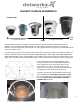
Cool Dome Installation Guidelines: The 400 BTU ‐ D2 Never apply high voltage power directly to the D2 Cool Dome inputs. The internal circuitry of the D2 was engineered for 12 VDC input ONLY. But, we do supply each Cool Dome with an external high voltage power supply, the Dotworkz/ MeanWell S‐250‐12 Power supply, which converts the power to a low voltage 12 VDC output. This allows you to use high voltage to indirectly power the Cool Dome. It is a highly durable, heat tolerant, A/C to D/C Power converter.
Please do not attempt to mount the S‐250‐12 within the Cool Dome itself, due to the large amount of heat created by the power supply, will greatly reduce the cooling effect of the D2 Cool Dome’s heat pump.
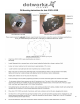
Excessive line drop for Wire Gauge and Distance Above includes 9 amps @ 12 vdc for D2 Cool Dome typical current draw, with 3 amps for max. camera & accessory draw. Voltage Drop Equation to Determine Minimum Wire Gauge to be Used on D/C run Between the S‐250‐12 Power Supply to D2 Cool Dome. Vd = voltage drop for 12vdc run (nominal) D = distance of run (ft) Vgm = gauge multiplier (vdc drop, per foot) Vd = D x Vgm Where we conservatively try to keep the voltage drop under 1.
Exploded View 29
Mounting Template 30