
Installation Manual

9
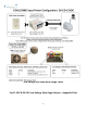
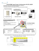
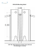
COOLDOME Input Power Configuration: D3-CD-12VDC
110 – 220 VAC Power Source
Single Phase Only
500 watt Step Down P/S
High Voltage to 12 VDC
Provided P/S: SP500
Must be Housed Indoors, or in
a NEMA Electrical Enclosure
Site Power Available
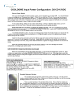
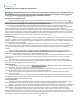
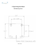
High Voltage A/C Input, Single Phase, USA Wiring Color Code
Color Symbol Terminal Description
Black L 1 Line Conductor, AKA Live, Hot
White N 2 Neutral Conductor
Green FG 3 FG, Field Ground, Chassis Ground
Front of Power Supply with terminal strip
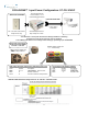
The D3 CD has two Coolers that run
independently.
To reduce low voltage current load, it is best to
run two pairs- individually –
So each 12VDC paired wiring runs load of one
cooler
Low Voltage 12 VDC Output Terminals
Color Symbol Terminals Description
Red +, V+ 9,10,11 Positive VDC
Black -. V- 12,13,14 Negative VDC
12 VDC Cable to
COOLDOME
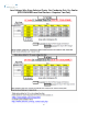
Turn Off Power or leave power disconnected during Installation of All Wiring.
Follow all local and relevant electrical codes & standards.
Test all Wiring and confirm correct voltages before wiring up & powering up COOLDOME.
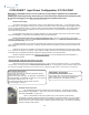
LOW VOLTAGE RUN
LOW VOLTAGE RUN: Wire Gauge Chart for D3-CD-12VDC: each cooler wired on independent 12VDC wire pairs
Wiring from Step Down P/S to D3 CD
Round, Water rated cable bundle,
such as SJOOW - 4 conductor
makes for an easy install and seal
into provided cable ports