PRODUCT INSTRUCTIONS D2 SERIES ENCLOSURES
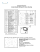
Table of Contents Limited Warranty Info ..………………………………………………………………………………………………………………………………………………………………………………... 0 Product Installation Precautions, Warnings, and Installation Guidelines ......................................................................................................... 1 D2 Component Checklist for camera installation / Camera Mount Bracket ..................................................................................................... 2 Intro to MVP Power .........................
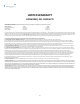
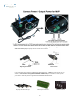
LIMITED WARRANTY DOTWORKZ, INC. PRODUCTS DOTWORKZ SYSTEMS INC. Warrants this Product to be free from defects in material or workmanship, as follows: PRODUCT CATEGORY All Enclosures and Electronics Power Supplies Accessory Brackets PARTS LABOR One (1) Year One (1) Year One (1) Year One (1) Year One (1) Year One (1) Year During the warranty period, to repair the Product the Purchaser will deliver it to Dotworkz Systems Inc. San Diego, CA, or return the defective product, freight prepaid.
PRODUCT INSTALLATION PRECAUTIONS – WARNINGS – ADDITIONAL INFORMATION (RETAIN THIS DOCUMENT) IMPORTANT SAFEGUARDS 1 Read Instructions - All the safety and operating instructions should be read before the unit is operated. 2 Retain Instructions -The safety and operating instructions should be retained for future reference. 3. Heed Warnings - All warnings on the unit and in the operating instructions should be adhered to. 4. Follow Instructions -All operating & user instructions should be followed. 5.
2
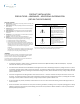
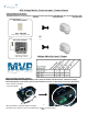
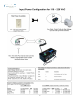
MVP Voltage Matrix: Enclosure Input – Camera Output Input Voltage to Enclosure The MVP Enclosures can be powered by Inputs of either High Voltage 110-220 VAC. Or Low Volt 24 VAC/ VDC Site Power Available 110 – 220 VAC Power Source – Single Phase Only Or Site Power Available 24 VAC/VDC Step Down Transformer High Voltage to 24 VAC Voltage Matrix for Input / Output Output Voltage to Power Camera MVP provides step down voltage to supply camera power for 12VDC, and 24V Cameras.
4
5
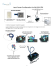
Camera Power Setup (STANDARD 12VDC CONNECTOR) All D2 environmental enclosures come standard with a 12VDC Right Angle Barrel Plug (3.3mm x 5.5mm with a 1mm center pin) for majority of the IP cameras on the market. Right Angle Standard Inline version If you IP camera’s power connector is different but still accepts up to ~ 13VDC for power, please see our section on Camera Power Setup (NON-STANDARD CONNECTOR) for instructions on how to power your camera.
7
Stand Off Assembly Key for Camera Height Adjustment Camera mount stand offs can be adjusted to any height from 0” to 3.75” using assembly logic illustrated above. By utilizing both the camera mounts inside the D2; the upper mounts, and the lower mounts around the lens on hinged lower of D2, virtually any PTZ or Mini-Dome Camera can be mounted into the enclosure at any level.
9
Installing Camera Bracket 3. The 2.25" standoffs will be inserted on the upper portion of the D2. Axis 214 PTZ Required components (see component checklist): Part # 1,3,5,12,14,15,& 16 Picture represents standoff location & orientation. Height of standoffs will vary depending on camera used. 4. Now slide the camera bracket with the camera into place to line up with 4 screws holes from the standoffs. 5. Use (4) #8-32 screws (Phillips head) to secure the bracket into place.
11
Installing Camera Bracket Axis 233D PTZ Align these 2 holes with the D2 bracket holes for the Axis 233D Required components (see component checklist): Part # 1,2,3,9,10,11,& 12 Axis 233D Ceiling bracket that came with the camera. *This is a required item for installation* 2. Do this by aligning the two holes on the D2 camera bracket with the Axis ceiling bracket adapter.
Installing Camera Bracket Axis 233D PTZ Continued . . . . . . . . 6. Now slide the camera bracket with the camera into place to line up with 4 screws holes from the standoffs. 7. Use (4) #8-32 screws (Phillips head) to secure the bracket into place. Picture represents standoff location & camera bracket orientation. Height of standoffs will vary depending on camera used. Tip: Insert (2) #8-32 screws in the front two standoffs to provide a guide to slide the camera bracket into.
Installing Camera Bracket 3. The 2" standoffs will be inserted on the lower lens portion of the D2. Canon VB-C300 Required components (see component checklist): Part# 1,2,3,5,6,7,& 8 Picture represents standoff location & orientation. Height of standoffs will vary depending on camera used. 4. Now slide the camera bracket with the camera into place to line up with 4 screws from the standoffs. This edge nests in arch at front of D2 5. Secure the plate by using (4) .
Installing Camera Bracket 3. The 2.5" standoffs will be inserted on the lower lens portion of the D2. Panasonic NS-202 Required components (see component checklist): Part# 1,2,4,5,6,7,& 8 Picture represents standoff location & orientation. Height of standoffs will vary depending on camera used. 4. Now slide the camera bracket with the camera into place to line up with 4 screws from the standoffs. This edge nests in arch at front of D2 5. Secure the plate by using (4) .
Installing Camera Bracket 3. The 2.0" standoffs will be inserted on the lower lens portion of the D2. Panasonic BB-HCM381/ 580/581 & KX-HMC280 Required components (see component checklist): Part# 1,2,3,5,6,7,& 8 Picture represents standoff location & orientation. Height of standoffs will vary depending on camera used. 4. Now slide the camera bracket with the camera into place to line up with 4 screws from the standoffs. This edge nests in arch at front of D2 5. Secure the plate by using (4) .
Installing Camera Bracket 2. The Sony RZ25N camera requires a 1.25" spacing for optimal fit and operation. Use (1) .75" standoffs and (1) .5" standoffs that are provided to create a 1.25" standoff. You will need to create 4 of these with the included hardware. Sony RZ25N Required components (see component checklist): Part # 1,2,3,12,14,15,& 16 .75' .5" 3. The 1.25" standoffs will be inserted on the upper portion of the D2. Picture represents standoff location & orientation.
Installing Camera Bracket 3. The Sony RZ30N camera requires a 2.25" spacing for optimal fit and operation. Use (1) 1.5" standoffs and (1) .75" standoffs that are provided to create a 2.25" standoff. You will need to create 4 of these with the included hardware. Sony RZ30N Required components (see component checklist): Part # 1,2,3,6,7,8,12, & 14 1.5" .75" 4. The 2.25" standoffs will be inserted on the upper portion of the D2. Picture represents standoff location & orientation.
Installing Camera Bracket 3. The 2.5" standoffs will be inserted on the upper portion of the D2. Sony RZ50N Required components (see component checklist): Part # 1,4,5,6,7,8,& 12 Picture represents standoff location & orientation. Height of standoffs will vary depending on camera used. 4. Now slide the camera bracket with the camera into place to line up with 4 screws holes from the standoffs. 5. Use (4) #8-32 screws (Phillips head) to secure the bracket into place.
Installing Camera Bracket 3. The .5" standoffs will be inserted on the upper portion of the D2. Sony RX550N Required components (see component checklist): Part # 1,2,12,14,15, & 16 Picture represents standoff location & orientation. Height of standoffs will vary depending on camera used. 4. Now slide the camera bracket with the camera into place to line up with 4 screws holes from the standoffs. 5. Use (4) #8-32 screws (Phillips head) to secure the bracket into place.
Installing Camera Bracket Toshiba WB21A Required components (see component checklist): Part # 1,2,3,4,5,6,14,15,16,& 17 Align these 4 holes with the D2 bracket holes for the Toshiba WB21A 2. Do this by aligning the four holes on the D2 camera bracket with the Toshiba ceiling bracket adapter. Use (4) m3-.5 ½” long screws, (4) m3 external lock washer, (4) m3 1/8" washers, and (4) m3 lock nuts that are included to secure the toshiba ceiling adapter to the D2 camera bracket.
Installing Camera Bracket Toshiba WB21A Continued . . . . . . . . 5. The 2.75" standoffs will be inserted on the lower portion of the D2. Picture represents standoff location & orientation. Height of standoffs will vary depending on camera used. 6. Now slide the camera bracket with the camera into place to line up with 4 screws from the standoffs. 7. Secure the plate by using (4) 1.0" standoffs to lock the bracket in place. The two front location will require the use of (2) .25" washer. See picture.
23
24
Optional Steady Step Mounting System Steady Step Bracket Steps adjust in ¼” increments. To adjust 1/8” between step settings, add 1/8” brass male-male hex stand-off (ITEM NO. 6) shown in detail D, by threading on top of movable slide bracket, then fastening camera bracket (CB-1007 or AB-1007).
26
27
D2 Exploded Detail 28
D2 Mounting Detail 29