INSTALLATIEVOORSCHRIFTEN EN GEBRUIKSAANWIJZING INSTALLATION INSTRUCTIONS AND OPERATING MANUAL INSTALLATION ET MODE D’EMPLOI EINBAUANLEITUNG UND GEBRAUCHSANWEISUNG INSTRUCCIONES DE INSTALACIÓN Y USO ISTRUZIONI PER L'INSTALLAZIONE E L'USO HOUTKACHEL WOOD STOVE POELE A BOIS HOLZ-FEUERSTÄTTE ESTUFA DE LEÑA STUFA A LEGNA Inbouwhaard 2175CBS, 2176CBS, 2175CBS3, 2576CBS en 2575CBS3 03.27663.
Inhoudsopgave Inleiding 3 Conformiteitsverklaring 3 Veiligheid 4 Installatiecondities 4 Algemeen Schoorsteen Ventilatie van de ruimte Vloer en wanden Productbeschrijving Installatie Voorbereiding Buitenluchtaansluiting toepassen Inbouwen in een nieuwe schouw Gebruik Eerste gebruik Brandstof Aanmaken Stoken met hout Regeling van de verbrandingslucht Doven van het vuur Ontassen Nevel en mist Eventuele problemen Onderhoud Schoorsteen Schoonmaken en ander regelmatig onderhoud 2 4 4 5 6 6 7 7 8 8 11 11
Inleiding Conformiteitsverklaring Geachte gebruiker, Met de aankoop van dit verwarmingstoestel van DOVRE heeft u gekozen voor een kwaliteitsproduct. Dit product maakt deel uit van een nieuwe generatie energiezuinige en milieuvriendelijke verwarmingstoestellen. Deze toestellen maken optimaal gebruik van zowel convectiewarmte als stralingswarmte. Uw DOVRE toestel is geproduceerd met de modernste productiemiddelen.
Veiligheid Let op! Alle veiligheidsvoorschriften moeten strikt worden nageleefd. Lees aandachtig de instructies voor installatie, gebruik en onderhoud voordat u het toestel in gebruik neemt. Het toestel moet worden geïnstalleerd overeenkomstig de wetgeving en voorschriften van uw land. Alle lokale bepalingen en de bepalingen die betrekking hebben op nationale en Europese normen moeten worden nageleefd bij het installeren van het toestel.
De schoorsteen moet luchtdicht en goed gereinigd zijn en voldoende trek garanderen. Een trek/onderdruk van 15 - 20 Pa tijdens normale belasting is ideaal. De schoorsteen moet - vertrekkend van de uitgang van het toestel - zo verticaal mogelijk lopen. Richtingsveranderingen en horizontale stukken verstoren de afvoer van verbrandingsgassen en veroorzaken mogelijk roetophoping. De binnenmaten mogen niet te groot zijn, om te voorkomen dat de verbrandingsgassen te sterk afkoelen waardoor de trek minder wordt.
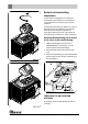
Vloer en wanden 1. Aansluitkraag 2. Rookvang De vloer waarop het toestel wordt geplaatst, moet voldoende draagvermogen hebben. Voor het gewicht van het toestel: zie de bijlage "Technische gegevens". 3. Deur 4. Stookbodem In de vloer onder het toestel en in de wanden rond het toestel mogen zich geen elektrische leidingen bevinden. 5. Grendel Onder het toestel moeten alle brandbare materialen verwijderd zijn of beschermd zijn met minimaal 6 cm betonplaat en 10 cm isolatie. 7.
zijpaneel. Het zijpaneel is optioneel verkrijgbaar. De instructies voor de ombouw van het toestel van zijglas naar gietijzeren zijpaneel worden met het paneel meegeleverd. 2. Neem eerst de binnenplaten aan de beide zijkanten uit het toestel. Bij de modellen 2175CBS3 en 2575CBS3 in de uitvoering met het zijglas, zijn deze binnenplaten afwezig. Installatie 3. Neem de binnenplaten die zich links en rechts aan de achterzijde bevinden uit het toestel. Voorbereiding 4.
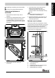
Buitenluchtaansluiting toepassen Als het toestel wordt geplaatst in een ruimte die onvoldoende is geventileerd, kunt u de aansluitset voor het aanvoeren van buitenlucht op het toestel aansluiten. De luchtaanvoerbuis heeft een diameter van 100 mm. Bij toepassing van een gladde buis mag deze buis maximaal 12 meter lang zijn. Bij gebruik van hulpstukken zoals bochten moet u per hulpstuk de maximale lengte (12 meter) met 1 meter verminderen. Buitenluchtaansluiting via de wand of de vloer en de aansluitkraag 1.
De plaatsing en aansluiting van de inbouwhaard De schouw rond de inbouwhaard opbouwen. Inbouwhaard plaatsen en aansluiten 1. Zet het toestel op de juiste hoogte, vlak en waterpas. 2. Zorg dat tussen de bestaande wanden, voorzien van de benodigde isolatie (zie het hoofdstuk "Installatiecondities"), en de achterkant van het toestel 100 mm vrije afstand is; zie de volgende twee figuren. 4.
Volg bij de bouw van de schouw de volgende voorschriften voor de convectieruimte: Extra bekleding van de convectieruimte voorkomt onnodige warmteuitstraling naar mogelijke buitenmuren en/of naast gelegen ruimtes. Het voorkomt ook aantasting van de spouwmuurisolatie. De bovenzijde van de convectieruimte moet luchtdicht afgesloten zijn met een afsluitplaat van onbrandbaar en hittebestendig materiaal.
C Afdekplaat D Isolatie 10 cm E Onbrandbare muur min. 10cm (bv. gasbeton) Behandeld hout, zoals sloophout, geverfd hout, geïmpregneerd hout, verduurzaamd hout, multiplex en spaanplaat. F Brandbare muur Kunststof, oud papier en huishoudelijk afval. G Convectieruimte H Onbrandbaar plafond I Brandbaar plafond J Uitlaat convectielucht K Isolatie L Onbrandbare vloer M Brandbare vloer N Opening ter voorkoming van drukopbouw O Aansluitbuis Afwerking 1.
Bij een losse stapeling verbrandt het hout vlug omdat de zuurstof elk stuk hout gemakkelijk kan bereiken. Gebruik een losse stapeling als u kort wilt stoken. Compacte stapeling 4. Sluit de deur van het toestel en zet de primaire luchtinlaat en de secundaire luchtinlaat van het toestel open; zie volgende figuur. 5. Laat het aanmaakvuur flink doorbranden totdat het een gloeiend houtskoolbed is geworden. Hierna kunt u een volgende vulling doen en het toestel gaan regelen; zie de paragraaf "Stoken met hout".
De primaire luchtschuif (A) regelt de lucht onder het rooster. De secundaire luchtschuif (B) regelt de lucht voor het glas (air-wash). Draai de luchtschuif (A) naar links om de luchtschuif te openen; zie volgende figuur. afzetten op de ruit en deur van het toestel. Bij een milde buitentemperatuur is het dus beter om het toestel een paar uur intens te laten branden, dan lange tijd laag te stoken. Regel de luchttoevoer met de secundaire luchtinlaat.
aanpassing kan de gewone stofzuiger ernstig beschadigen. 3. Sluit de deur van het toestel. As verwijderen bij de modellen 2176 en 2576 Schoorsteen In veel landen bent u wettelijk verplicht de schoorsteen te laten controleren en onderhouden. Aan het begin van het stookseizoen: laat de schoorsteen vegen door een erkend schoorsteenveger. Tijdens het stookseizoen en nadat de schoorsteen lange tijd niet is gebruikt: laat de schoorsteen controleren op roet.
de plaat de warmte niet meer afgeven aan de omgeving en kan de plaat vervormen of scheuren. Laat het toestel nooit branden zonder de vuurvaste binnenplaten. Klep en vlamplaat demonteren Zowel de klep als de vlamplaat zijn demontabel. De klep (A) is met de klepstang (B) verbonden aan de vlamplaat. De vlamplaat is met een boutverbinding (C) aan het toestel bevestigd; zie volgende figuur. 3. Om de vlamplaat te verwijderen moet eerst de boutverbinding (C) los geschroefd worden.
Smeer de bewegende delen (zoals geleidersystemen, scharnierpennen, grendels en luchtschuiven) met hittevast vet dat verkrijgbaar is bij de vakhandel. Afwerklaag bijwerken Kleine lakbeschadigingen kunt u bijwerken met een spuitbus speciaal hittebestendige lak die verkrijgbaar is bij uw leverancier. Afdichting controleren Monteer voordat u het toestel in gebruik neemt de vlamplaat en de klep. Volg voor de montage van de klep en de vlamplaat bovenstaande instructies in omgekeerde volgorde.
Bijlage 1: Technische gegevens Model Series 2170CB en 2570CB Nominaal vermogen 10 kW Schoorsteenaansluiting (diameter) 150 mm Gewicht +/- 160 kg Aanbevolen brandstof Hout Kenmerk brandstof, max.
Bijlage 2: Afmetingen 2175CBS 09.20017.
2176CBS 09.20017.
2175CBS3 09.20017.
2576CBS 09.20017.
2575CBS3 09.20017.
Bijlage 3: Afstand tot brandbaar materiaal Minimale ventilatieruimte buiten het stralingsbereik Afmetingen onbrandbare vloerplaat in centimeters Minimale afmetingen onbrandbare vloerplaat V > H + 30 > 60 S > H + 20 > 40 Wijzigingen op grond van technische verbeteringen voorbehouden 23
Bijlage 4: Diagnoseschema Probleem Hout wil niet doorbranden Geeft onvoldoende warmte Rookterugslag tijdens het bijvullen Toestel brandt te hevig, niet goed regelbaar Aanslag op het glas 24 mogelijke oorzaak mogelijke oplossing Onvoldoende trek Een koude schoorsteen creëert vaak onvoldoende trek. Volg de instructies voor het aanmaken in het hoofdstuk "Gebruik"; open een raam. Hout te vochtig Gebruik hout met maximaal 20% vocht. Afmetingen hout te groot Gebruik kleine stukjes aanmaakhout.
Index D Aanmaakhout 24 Deur afdichtingskoord draairichting wijzigen Aanmaakvuur 11 Draagvermogen van vloer 6 Aansluiten afmetingen 18 Draairichting wijzigen 6 A Aansluiten op buitenluchtaanvoer 8 Aansluitkraag 7 16 6 11 Drogen van hout G Aansteken 11 Afdichtingskoord van deur 16 Geschikte brandstof 11 Afmetingen 18 Gewicht 17 Afsluitplaat convectieruimte 10 Afwerklaag, onderhoud 16 Glas aanslag schoonmaken 24 16 As verwijderen 13 Aslade openen 14 B Beluchting van het
Muren brandveiligheid 6 N aansluiting op hoogte onderhoud voorwaarden 9 5 14 4 Naaldhout 11 Schoorsteenbrand voorkomen Nat hout 11 Schoorsteenkap Nevel, niet stoken 14 Secundaire luchtinlaat 12 Smeren 16 Stof-emissie 17 14, 17 Nominaal vermogen O Onderhoud afdichting glas schoonmaken schoorsteen smeren toestel schoonmaken vuurvaste binnenplaten 16 16 14 16 14 14 Ongeschikte brandstof 11 Ontassen 13 Ontassingsluik 14 Openen aslade ontassingsluik 14 14 Opslag van hout 11 Stoken
Vuurvaste binnenplaten onderhoud waarschuwing 14 11 W Waarschuwing brandbare materialen glas gebroken of gebarsten heet oppervlak kachelruitreiniger schoorsteenbrand ventilatie verzekeringsvoorwaarden voorschriften vuurvaste binnenplaten Wanden brandveiligheid 4 4, 16 4 16 4, 11, 13 4-5 4 4 11 6 14, 24 Warmte, onvoldoende Weersomstandigheden, niet stoken 14 Z Zijglas 6 Zijpaneel ombouw 6 Wijzigingen op grond van technische verbeteringen voorbehouden 27
Table of contents Introduction 3 Declaration of conformity 3 Safety 4 Installation conditions 4 General Flue or chimney Ventilation of the area Floors and walls Product description 4 4 5 5 6 Installation Preparation Fitting the outside air intake duct Building into a new hearth Use First use Fuel Lighting Burning wood Controlling the air Extinguishing the fire Removing ashes Fog and mist Solving problems Maintenance Chimney Cleaning and other regular maintenance activities 2 7 7 8 8 11 11 11 11
Introduction Dear user, In buying this DOVRE heating appliance, you have chosen a high quality product. This product is part of a new generation of energy saving and environmentally friendly heating appliances. These appliances make optimal use of convection heat as well as thermal radiation (radiant heat). Your DOVRE appliance has been manufactured with state-of-the-art production equipment. In the unlikely event of a malfunction, you can always rely on DOVRE for support and service.
Safety Please note: All safety regulations must be complied with strictly. Carefully read the instructions for installation, use and maintenance before you start using the appliance. The appliance must be installed in accordance with the laws and requirements of your country. All local regulations and the regulations relating to national and European standards must be observed when installing the appliance. Read the instructions for installation, use and maintenance supplied with the appliance.
The flue or chimney must be airtight and well cleaned and guarantee sufficient draught. A draught/vaccuum of 15 - 20 Pa during normal operation is ideal. Starting from the flue spigot, the flue must run as vertically as possible. Changes in direction and horizontal pieces disrupt the outward flow of combustion gases and may cause the deposit of soot. The interior measurements should not be too big, to prevent the combustion gases from cooling down too much, thereby reducing the draught.
around it. 5. Latch Below the stove, all combustible materials must be removed or protected by at least 6 cm of concrete and 10 cm of insulation. 6. Primary air slide Combustible walls adjacent to the appliance must be protected with a brick wall of at least 10 cm and 10 cm of insulation. Protect non-combustible walls adjacent to the appliance with at least 2.5 cm of insulation to prevent cracking. Protect a combustible floor against radiated heat and ash with a fireproof floor plate.
Installation Preparation Please check the appliance for damage caused during transport or any damage or defects immediately after delivery. If you detect damage caused during transport or any other damage or defects, do not use the appliance and notify the supplier. Remove the removable parts (fire-resistant inner plates, fire compartment, fire basket, ash removal port and ash pan) from the appliance before you start installing the appliance.
Fitting the outside air intake duct If the appliance is installed in a room without sufficient ventilation, you can install the connecting kit on the appliance for the supply of outside air. The air supply tube has a diameter of 100 mm. If installing a smooth tube, it may be no longer than 12 m. If accessories such as bends are used, the maximum length (12 m) must be reduced by 1 m for each accessory used. Outside air intake duct through the wall or the floor and the connection collar 1.
Placing and connecting the stove 1. Put the appliance at the right height and level it. 2. Check that there is a clearance of 100 mm between the existing walls, which must have the necessary insulation (see chapter "Installation Conditions"), and the back of the appliance; see the next two figures. In the case of new masonry, wait until the masonry has dried sufficiently. 5. On the outside air connection: connect the outside air intake to the connection kit you have fitted to the appliance.
The top of the convection space must be closed airtight by means of a closing plate of incombustible and heat-resistant material. 4. Build the rest of the hearth up to the flue gas hole in the ceiling. The masonry may not rest on the stove. Use a support such as a steel beam. Leave a clearance of at least 3 mm between the support and the appliance. The cover plate must be level and placed at least 30 cm below the flue opening in the ceiling.
H Fireproof ceiling I Combustible ceiling J Convection air outlet K Insulation L. Fireproof floor M Combustible floor N Opening to prevent pressure build-up O Connection pipe Finish 1. Put all dismantled parts back into the appliance in their correct places. 2. Ensure that the newly built hearth is dry enough before firing the stove. Never light a fire in the appliance without the fireproof inner plates. The appliance is now ready for use.
If the logs are stacked openly, the wood will burn quickly as the oxygen can reach each log easily. If you want to use the stove for a short while, make an open stack. Compact stacking 4. Close the door of the appliance and open the primary air inlet and the secondary air inlet of the appliance; see the following figure. 5. Let this fire develop into a good blaze until there is glowing bed of charcoal. You can then add fuel and adjust the appliance, see the chapter "Stoking with wood".
The primary air slide (A) regulates the air below the grate. The secondary air slide (B) regulates the air for the glass (air wash). Turn the air slide (A) to the left to open it; see next figure. intensely, so that layers of tar and creosote disappear. Low intensity fires also cause tar deposits on the stove window and door. When the outside temperature is not very low, it is better to burn wood intensely for a few hours instead of having a low intensity fire for a long period of time.
Always use an ash vacuum cleaner; using an ordinary vacuum cleaner that has not been specially modified can cause serious damage to an ordinary vacuum cleaner. Maintenance Follow the maintenance instructions in this chapter to keep the appliance in good condition. 3. Close the door of the appliance. Chimney Ash removal in models 2176 and 2576 In many countries, people are legally required to have their chimney checked and maintained.
Cast-iron inner plates go a long way if you frequently remove the ash that may pile up behind them. If accumulated ash behind a cast-iron plate is not removed, the plate cannot dissipate the heat anymore to its surroundings and that may cause the plate to warp or crack. 2. The damper is now loose. Take the damper out of the appliance; see next figure. Never use the appliance without the fireresistant inner plates. Dismantling damper and baffle plate Both the damper and the baffle plate can be removed.
5. The baffle plate is now loose. Carefully take the baffle plate out of the appliance; see next figure. Lubrication Although cast-iron is slightly self-lubricating, you will still have to lubricate moving parts frequently. Lubricate the moving parts (such as guide systems,hinge pins, latches and air slides) with heat resistant grease that is available in the specialist trade.
Appendix 1: Technical Data Model Series 2170CB and 2570CB Rated output 10 kW Chimney connection (diameter) 150 mm Weight +/- 160 kg Recommended fuel Wood Fuel property, max. length 50 cm Flue gas flow rate 10.
Appendix 2: Dimensions 2175CBS 09.20017.
2176CBS 09.20017.
2175CBS3 09.20017.
2576CBS 09.20017.
2575CBS3 09.20017.
Appendix 3: Distance from combustible material Minimum ventilation outside the radiation range Dimensions fireproof floor plate in centimetres Minimum dimensions fireproof floor plate V > H + 30 > 60 S > H + 20 > 40 Subject to change because of technical improvements 23
Appendix 4: Diagnostic diagram Problem Wood does not keep burning Gives off insufficient heat Smoke emissions into the room when adding wood Fire in appliance is too intense, is hard to adjust Deposit on the glass 24 Possible cause Possible solution Insufficient draught A cold flue usually fails to create sufficient draught. Follow the instructions for lighting in the "Use" chapter; open a window. Wood too damp Use wood with no more than 20% moisture.
Index Cleaning appliance 14 13 Closing plate convection space 10 Adding wood smoke emissions into the room 24 Combustible material distance from 23 Air control 12 Connection collar 7 Connection to supply of outside air 8 A Adding fuel Air inlet grate placing requirements 10 10 Connections dimensions 18 Air inlets 12 Control air supply 13 Air leak 16 Control of air 12 Air outlet grate placing requirements 10 10 Convection space cover plate instructions 10 9 Air supply for fir
Fireproof inner plates warning sealing 11 Floors fire safety 16 Mist, do not burn wood 14 N 5 Nominal output Flue maintenance requirements 14 4 14 14 Opening ashpan 14 13 12 14 11 11 Outside air intake connection to 17 Fog, do not burn wood G Glass clean deposit O Open ash removal port Flue gas flow rate Fuel adding adding wood necessary amount suitable unsuitable 14 16 24 9 P Paint finish 11 Particulate emission 17 Placing dimensions 18 Prevent a chimney fire 13 Primary air i
Suitable fuel 11 Supply of outside air 5, 8 Sweep chimney 14 Swing direction changing 6 T Tar 13 Temperature 17 Temperature rise measuring section 17 U Unsuitable fuel 11 V Ventilation connect supply of outside air rule of thumb 5 8 5 Ventilation louvre 5 W Walls fire safety Warning chimney fire combustible materials fireproof inner plates glass broken or cracked hot surface regulations stove window cleaner terms and conditions for insurance ventilation 5 4, 11, 13 4 11 4, 16 4 4 16 4 4
Table des matières Introduction 3 Déclaration de conformité 3 Sécurité 4 Conditions d'installation 4 Généralités Cheminée Ventilation de la pièce Sols et murs Description produit 4 4 5 6 6 Installation Préparation Réalisation d'un raccordement d'air extérieur Encastrement dans un nouveau manteau de cheminée Utilisation Première utilisation Combustible Allumage La combustion au bois Réglage de l'air de combustion Extinction du foyer Décendrage Brouillard et brume Résolution problèmes Entretien 2
Introduction Chère utilisatrice, cher utilisateur, En achetant ce poêle DOVRE, vous avez opté pour un produit de qualité. Ce produit fait partie d'une nouvelle génération d'appareils de chauffage écologiques et économiques en énergie. Ces appareils utilisent de manière optimale la chaleur convective, ainsi que la chaleur rayonnante. Votre poêle DOVRE est fabriqué avec les moyens de fabrication les plus modernes.
Sécurité Attention ! Toutes les consignes de sécurité doivent être strictement respectées. Avant d'utiliser votre poêle, lisez attentivement les instructions pour l'installation, l'utilisation et l'entretien. L'appareil doit être installé conformément à la législation et aux prescriptions nationales. Conditions d'installation Toutes les dispositions régionales et les dispositions concernant les normes européennes et nationales doivent être respectées lors de l'installation de l'appareil.
La cheminée doit satisfaire aux conditions suivantes : La cheminée doit être fabriquée en matériaux réfractaires, de préférence en acier inoxydable ou en céramique. La cheminée doit être étanche, bien propre et garantir un tirage suffisant. La règle de base est la suivante : 60 cm au-dessus du faîtage du toit. Si le faîtage du toit est éloigné de plus de 3 mètres de la cheminée : respectez les dimensions indiquées sur le croquis suivant. A = point le plus haut du toit à une distance de 3 mètres.
Vous pouvez également raccorder l'appareil à une arrivée d'air extérieur. Un kit de raccordement est fourni à cet effet. Dans un tel cas, une aération supplémentaire n'est pas nécessaire. Sols et murs Ne placez aucun matériau inflammable à moins de 50 cm des ouvertures d'évacuationconvection éventuelles. Description produit 09.20015.034 Le sol sur lequel l'appareil sera posé, doit présenté une capacité de charge suffisante.
Caractéristiques complémentaires des modèles 2175 et 2176 Les modèles sont dotés d'une buse de raccordement qui permet un raccordement à la verticale ou un raccordement 45°. Caractéristiques complémentaires des modèles 2176 et 2576 Les modèles sont dotés d'un bac à cendres amovible. Caractéristiques complémentaires modèle 2175CBS3 et modèle 2575CBS3 retirer toutes les pièces non fixées de l'appareil.
raccordement sur une évacuation de fumée existante, par exemple, vous devez tourner la buse de raccordement à 180° ; voir les deux illustrations suivantes. 1. Désaccouplez le raccord entre la buse de raccordement et le collecteur de fumée en dévissant les deux écrous M8. 2. Retirez la buse de raccordement hors des deux boulons. 3. Tournez la buse de raccordement de 180° et reposez-la sur le collecteur de fumée. 4. Réaccouplez la buse de raccordement et le collecteur de fumée en serrant les deux écrous M8.
2. Raccordez hermétiquement le tube d'évacuation d'air au mur. 3. Montez la buse de raccordement (A) sur l'extrémité filetée M6 (B) à l'aide de l'écrou (D) et de la rondelle (C) ; voir illustration suivante. Encastrement dans un nouveau manteau de cheminée L'installation de l'insert de cheminée/foyer fermé comprend deux phases : La mise en place et le raccordement du foyer fermé La construction du manteau de cheminée autour du foyer fermé. Pose et raccordement du foyer fermé 1.
pouvoir circuler librement. L'air pour la combustion doit pouvoir être aspiré correctement et l'air chauffé par le foyer fermé (air de convection) doit pouvoir s'échapper librement dans la pièce à chauffer ; voir illustration suivante. Des grilles d'arrivée d'air doivent être montées en bas du manteau de cheminée pour permettre l'alimentation en air ambiant. L'ouverture d'arrivée d'air minimale est de 250 cm2.
4. Maçonnez le manteau jusqu'à l'ouverture de gaz de fumée dans le plafond. cellulaire, par ex.) F Paroi inflammable Le foyer fermé ne doit pas supporter l'ouvrage en maçonnerie. Placez un support tel qu'un fer porteur. Veillez à respecter un jeu minimum de 3 mm entre le support et l'appareil. G Espace de convection H Plafond ininflammable 5. Fermez l'espace de convection avec la plaque de fermeture. 6. Placez les grilles d'évacuation d'air sous la plaque de fermeture. 7.
engendrer un départ de feu dans le conduit de cheminée : Bois traités, tels que bois de démolition, bois peint, bois imprégné, bois conservé, contreplaqué et aggloméré. 2. Empilez sur les bûches deux couches de bois d'allumage l'une sur l'autre en les croisant. 3. Posez un allume-feu dans la couche inférieure de bois d'allumage et allumez-le en suivant les instructions sur son emballage. Plastique, vieux papier et déchets ménagers.
Empilage non serré Remplissez au maximum un tiers du volume total du corps de chauffe. Réglage de l'air de combustion Le poêle est doté de différents dispositifs pour régler l'air (voir illustration). Quand le bois est empilé non serré, il brûlera vite du fait que l'oxygène pourra atteindre facilement chaque bûche. Un empilage de cette façon est recommandé si vous souhaitez chauffer pendant une période courte. Empilage serré Le registre d'air primaire (A) permet de régler l'air sous la grille.
Ouvrez temporairement l'arrivée d'air primaire si l'admission d'air par l'arrivée d'air secondaire est insuffisante ou si vous souhaitez raviver le feu. Remplir régulièrement avec une petite quantité de bûches de bois est mieux que de remplir avec une grosse quantité de bûches d'un coup. Extinction du foyer L'appareil est doté d'un déflecteur à double paroi avec ouvertures d'air permanentes qui garantissent une double combustion parfaite.
Décendrage des modèles 2176 et 2576 Entretien Pour conserver votre appareil en bon état, suivez les instructions d'entretien présentées dans ce chapitre. Conduit de cheminée Dans de nombreux pays, la loi impose le contrôle et l'entretien par un professionnel des conduits de cheminée. Au début de la saison de chauffe : faites ramoner votre conduit de cheminée par un spécialiste agréé. 1. Ouvrez la porte de l'appareil. 2. Utilisez la pelle pour ouvrir le volet de décendrage (C) dans le fond du poêle (A).
Voir le chapitre « Installation » pour consulter les instructions concernant la dépose et le remontage des plaques intérieures. Les plaques intérieures en vermiculite isolantes peuvent présenter des craquelures. Ces dernières ne nuisent cependant pas à la bonne fonction des plaques. Les plaques intérieures en fonte ont une durée de vie plus longue si vous retirez régulièrement la cendre qui s'accumule éventuellement derrière.
4. Soulevez l'avant du déflecteur, tirez-le vers l'avant et séparez-le du boulon ; voir illustration suivante. 3. Nettoyez une nouvelle fois la surface en verre avec un produit ordinaire de nettoyage du verre. 4. Nettoyez la surface en verre en la frottant avec un chiffon sec ou de l'essuie-tout. N'utilisez jamais de produits abrasifs ou mordants pour nettoyer la surface en verre. Portez des gants de nettoyage pour protéger vos mains.
Annexe 1 : Spécifications techniques Modèle Séries 2170CB et 2570CB Puissance nominale 10 kW Raccordement conduit de cheminée (diamètre) 150 mm Poids +/- 160 kg Combustible recommandé Bois Caractéristique combustible, longueur max.
Annexe 2 : Dimensions 2175CBS 09.20017.
2176CBS 09.20017.
2175CBS3 09.20017.
2576CBS 09.20017.
2575CBS3 09.20017.
Annexe 3 : Distance entre le poêle et les matériaux combustibles Espace de ventilation minimum hors de la plage de rayonnement Dimensions en centimètres du hourdis ignifugé Dimensions minimales du hourdis ignifugé V > H + 30 > 60 S > H + 20 > 40 24 Sous réserve de modifications dues à des améliorations techniques
Annexe 4 : Tableau de diagnostic Problème Le bois ne continue pas à brûler Dégage une chaleur insuffisante Retour de fumée lors du remplissage du poêle Le feu est trop vif, impossible de bien régler le poêle Dépôt sur la vitre cause possible solution éventuelle Tirage insuffisant Une cheminée froide présente souvent un mauvais tirage. Suivez les instructions concernant l'allumage dans le chapitre « Utilisation » ; ouvrez une fenêtre. Le bois est trop humide Utilisez du bois à 20 % d'humidité maximum.
Index Cheminée conditions hauteur raccordement à A Aération raccordement alimentation en air extérieur Aération du feu 8 14 Alimentation en air extérieur raccordement à 8 9 12 Allumage 5 5 9 Clapet montage 16 Combustible adapté inadapté quantité nécessaire remplissage 11 11 15 14 Arrivée d'air extérieur 5 Arrivée d'air primaire 12 Combustible adapté 11 Arrivée d'air secondaire 12 Combustible inadapté 11 Arrivées d'air 12 Augmentation de la température section de mesure 18 Combustio
nettoyage du verre plaques intérieures réfractaires 17 15 Espace de convection consignes plaque de fermeture 10 10 Éteindre le foyer 14 F Murs sécurité incendie 6 N Nettoyage poêle verre 15 17 nettoyant pour vitres de poêle 17 Feu allumage 12 Feu d'allumage 12 ouverture 15 Foyer extinction 14 Ouverture bac à cendres 15 Fuite d'air 17 Fumée lors de la première utilisation Ouvrir volet de décendrage 15 11 G Gaz de fumée 18 Goudron 14 Graissage 17 Graisse pour graissage 17 G
Réglage de l'arrivée d'air 14 Remplissage en combustible 14 Remplissage en matériau combustible retour de fumée 25 Rendement 18 Résolution de problèmes 25 4, 25 Retour de fumée S Séchage du bois 12 Sécurité incendie distance entre poêle / matériaux combustibles24 meubles 6 6 murs sol 6 Sens de rotation modification 6 Sols capacité de charge sécurité incendie 6 6 stockage du bois 12 T Tapis 6 Température 18 Tirage 18 V Ventilation règle de base 5 5 Verre dépôt nettoyage 25 17 Vitr
Inhaltsverzeichnis Einleitung 3 Konformitätserklärung 3 Sicherheit 4 Installationsbedingungen 4 Allgemeines Schornstein Belüftung des Raums Boden und Wände Produktbeschreibung Installation Vorbereitung Anwendung des Außenluftanschlusses Einbau in einen neuen Kamin Inbetriebnahme Erste Inbetriebnahme Brennstoff Anzünden Heizen mit Holz Regelung der Verbrennungsluft Löschen des Feuers Entaschen Nebel Eventuelle Probleme Wartung Schornstein Reinigung und andere Wartungsarbeiten 7 7 8 9 11 11 11 12 12
Einleitung Konformitätserklärung Sehr geehrte(r) Benutzer(in), Mit dem Kauf dieses Heizgeräts von DOVRE haben Sie sich für ein hochwertiges Produkt entschieden. Dieses Produkt gehört zu einer neuen Generation energiesparender und umweltfreundlicher Heizgeräte. Diese Geräte nutzen sowohl Konvektionswärme als auch Strahlungswärme. Ihr DOVRE-Gerät wurde mithilfe der modernsten Produktionsmittel gefertigt.
Sicherheit Achtung! Alle Sicherheitsvorschriften müssen strikt eingehalten werden. Lesen Sie die Anleitungen zu Installation, Inbetriebnahme und Wartung sorgfältig durch, bevor Sie das Gerät in Betrieb nehmen. Das Gerät muss gemäß den in Ihrem Land geltenden gesetzlichen Bestimmungen installiert werden. Alle lokalen Bestimmungen sowie Bestimmungen aufgrund von EU-Normen müssen bei der Installation des Geräts beachtet werden.
Der Schornstein muss aus feuerfestem Material bestehen, vorzugsweise aus Keramik oder Edelstahl. Der Schornstein muss luftdicht und gut gereinigt sein und vollständigen Zug garantieren. Wenn der Dachfirst mehr als 3 Meter vom Schornstein entfernt ist: halten Sie die in der folgenden Abbildung angegebenen Maße ein. A = der höchste Punkt des Daches innerhalb eines Abstands von 3 Metern. Ein Zug/Unterdruck von 15 - 20 Pa während der normalen Belastung ist ideal.
Sie können das Gerät auch an einer Außenluftanfuhr anschließen. Hierfür ist ein Anschlusssatz im Lieferumfang enthalten. Dann benötigen Sie keine zusätzliche Ventilation. Produktbeschreibung 09.20015.034 Boden und Wände Der Boden, auf dem das Gerät aufgestellt wird, muss über ein ausreichendes Tragvermögen verfügen. Für das Gewicht des Geräts vgl. die Anlage "Technische Daten". Im Boden unter dem Gerät und in den Wänden rund um das Gerät dürfen sich keine elektrischen Leitungen befinden.
Anschluss und für einen Anschluss im Winkel von 45° bietet. Ergänzendes Merkmal der Modelle 2176 und 2576 Die Modelle verfügen über eine herausnehmbare Aschenlade. Ergänzende Merkmale der Modelle 2175CBS3 und 2575CBS3 Entfernen der feuerfesten Innenplatten Entfernen Sie die feuerfesten Innenplatten in der richtigen Reihenfolge, gemäß der nachfolgenden Anleitung: 1. Öffnen Sie die Tür, indem Sie den Riegel nach außen drehen und die Tür so entriegeln; vgl. die nachfolgende Abbildung.
die zwei Muttern M8 losdrehen. 2. Kippen Sie das Anschlussstück von den beiden Bolzen weg. 3. Drehen Sie das Anschlussstück um 180°, und setzen Sie es wieder auf den Rauchfang. 4. Verbinden Sie das Anschlussstück und den Rauchfang wieder, indem Sie die zwei Muttern M8 festdrehen. 5. Dichten Sie den Zwischenraum zwischen dem Anschlusstück und dem Rauchfang mit Ofenkitt ab. Der Ofenkitt gehört nicht zum Lieferumfang des Geräts.
2. Schließen Sie das Luftzufuhrrohr hermetisch mit der Wand ab. 3. Montieren Sie das Anschlussstück (A) auf dem Gewindeende M6 (B) mithilfe der Mutter (D) und des Verschlussrings (C); vgl. die nachfolgende Abbildung. Einbau in einen neuen Kamin Die Installation des Einbauofens besteht aus zwei Teilen: Der Platzierung und dem Anschluss des Einbauofens Dem Aufbau des Kamins um den Einbauofen Platzierung und Anschluss des Einbauofens 1.
die Verbrennung muss Luft angesaugt werden, und die vom Einbauofen erwärmte Luft (die Konvektionsluft) muss frei in den zu heizenden Raum strömen können; vgl. die nachfolgende Abbildung. der Unterseite des Kamins Lufteinslassroste befinden. Eine Lufteinlassöffnung muss mindestens eine Fläche von 250 cm2 haben. Wenn der Raum nicht ausreichend belüftet ist, müssen Sie mithilfe des mitgelieferten Außenluftanschlusssets oder eines optionalen Luftklappensets mit Regelknopf für die Anfuhr von Außenluft sorgen.
Porenbeton) 4. Mauern Sie den Kamin weiter auf bis zur Rauchgasöffnung in der Decke. Der Einbauofen darf nicht das Mauerwerk tragen. Verwenden Sie eine Stütze, wie etwa ein Trageisen. Lassen Sie zwischen der Stütze und dem Gerät mindestens 3 mm Spiel. 5. Schließen Sie den Konvektionsraum mit der Abschlussplatte ab. 6. Platzieren Sie die Luftauslassroste unter der Abschlussplatte. 7. Stellen Sie oberhalb der Abschlussplatte eine Öffnung her, um eventuellen Druckaufbau zu verhindern.
Behandeltes Holz, wie etwa Holz mit Beschichtungen, gefärbtes Holz, imprägniertes Holz, konserviertes Holz, Multiplex und Spanplatten. Kunststoff, Altpapier und Haushaltsabfälle. 2. Stapeln Sie auf den Holzstücken zwei Lagen Anzündehölzchen kreuzweise übereinander. 3. Legen Sie den Anzünderblock zwischen die unterste Lage von Anzündehölzchen, und zünden Sie den Anzünderblock gemäß der Anleitung auf der Verpackung an.
Lose Stapelung Regelung der Verbrennungsluft Das Gerät verfügt über verschiedene Einrichtungen für die Luftregelung (vgl. die Abbildung). Bei einer losen Stapelung verbrennt das Holz schnell, da der Sauerstoff jedes Holzstück einfach erreichen kann. Stapeln Sie das Holz lose, wenn Sie kurz heizen möchten. Kompakte Stapelung Die primäre Luftklappe (A) regelt die Luft unter dem Rost. Die sekundäre Luftklappe (B) regelt die Luft vor dem Glas (Air-Wash).
Das Gerät verfügt über eine doppelwandige Flammplatte mit permanenten Luftöffnungen, die für die Nachverbrennung sorgen. Hinweise Heizen Sie niemals mit geöffneter Tür. Heizen Sie das Gerät regelmäßig gut durch. Wenn Sie lange mit niedriger Flamme heizen, können sich im Schornstein Ablagerungen von Teer und Carbolineum (Steinkohlenteer) bilden. Diese Stoffe sind leicht brennbar.
1. Öffnen Sie die Tür des Geräts. 2. Öffnen Sie mit der Zugschaufel die Entaschungsklappe (C) im Boden (A). 3. Schieben Sie die Asche mit der Zugschaufel durch die Entaschungsöffnung in die darunter befindliche Aschenlade (B). Reinigung und andere Wartungsarbeiten Reinigen Sie das Gerät nicht, so lange es noch warm ist. Reinigen Sie die Außenseite des Geräts mit einem trockenen und fusselfreien Tuch. 4. Schließen Sie die Entaschungsöffnung. 5.
(B) mit der Flammplatte verbunden. Die Flammplatte ist mithilfe einer Bolzenverbindung (C) am Gerät befestigt; vgl. die nachfolgende Abbildung. 3. Zur Entfernung der Flammplatte müssen Sie zuerst die Bolzenverbindung (C) losschrauben. Drehen Sie die Mutter los; vgl. die nachfolgende Abbildung. 1. Kippen Sie die Klappe (A) nach oben, und entfernen Sie die Klappenstange (B) von der Klappe. Kippen Sie die Klappe zur Rückseite des Geräts; vgl. die nachfolgende Abbildung. 4.
5. Die Flammplatte ist jetzt frei. Nehmen Sie die Flammplatte vorsichtig aus dem Gerät; vgl. die nachfolgende Abbildung. ausgetauscht werden, bevor das Gerät erneut in Betrieb genommen wird. Achten Sie darauf, dass kein Ofenscheibenreiniger zwischen das Glas und die gusseiserne Tür läuft. Schmieren Obwohl Gusseisen eigentlich "selbstschmierend" ist, müssen bewegliche Teile doch regelmäßig geschmiert werden. Montieren Sie vor der Inbetriebnahme des Geräts die Flammplatte und die Klappe wieder an.
Anlage 1: Technische Daten Modell Serie 2170CB und 2570CB Nominalleistung 10 kW Schornsteinanschluss (Durchmesser) 150 mm Gewicht +/- 160 kg Empfohlener Brennstoff Holz Kennzeichen Brennstoff, max.
Anlage 2: Abmessungen 2175CBS 09.20017.
2176CBS 09.20017.
2175CBS3 09.20017.
2576CBS 09.20017.
2575CBS3 09.20017.
Anlage 3: Abstand zu brennbarem Material Minimaler Belüftungsraum außerhalb des Strahlungsbereichs Abmessungen der feuerfesten Bodenplatte in Zentimetern Mindestabmessungen feuerfeste Bodenplatte V > H + 30 > 60 S > H + 20 > 40 24 Änderungen aufgrund technischer Verbesserungen vorbehalten
Anlage 4: Diagnoseschema Problem Holz brennt nicht durch Liefert nicht ausreichend Wärme Rauchrückschlag beim Nachfüllen Gerät brennt zu stark, nicht gut regelbar Flammenanschlag an das Glas Mögliche Ursache Mögliche Lösung Nicht ausreichender Zug Ein kalter Schornstein führt zu unzureichendem Zug. Folgen Sie der Anleitung zum Anzünden im Kapitel "Verwendung"; öffnen Sie ein Fenster. Holz zu feucht Verwenden Sie nur Holz mit max. 20 % Feuchtigkeit.
Index Brennstoffe geeignete A C Abdichtungsschnur der Tür 17 Abgas Massenfluss 18 Abmessungen 19 Abschlussplatte Konvektionsraum 10 Achtung Ventilation Versicherungsbedingungen Anschluss Abmessungen 11 Carbolineum 14 D Drehrichtung ändern 6 E 5 4 Entaschen 14 Entaschungsklappe 15 19 Entfernen Asche 14 Anschluss an Außenluftzufuhr 8 Anschlussstück 7 F Anstecken 12 Fegen des Schornsteins 15 Anzündeholz 25 Anzündfeuer 12 Asche entfernen 14 Aschenlade öffnen 15 Feuer an
nass trocknen 12 12 13 Holzstücke stapeln I Ö Öffnen Aschenlade Entaschungsklappe 15 15 P Innenplatten entfernen 7 Innenplatten, feuerfeste 7 Primärer Lufteinlass Probleme lösen K 15, 25 R Klappe montieren 15 Konvektionsraum Abschlussplatte Vorschriften 10 10 L Lack 11 Lagerung von Holz 12 Luftauslassrost Anforderungen Platzierung 10 10 Lufteinlässe 12 Lufteinlassrost Anforderungen Platzierung 10 10 Luftleck 17 Luftzufuhr regeln 14 M Mauern Brandsicherheit 12 6 N Rauch bei e
Tür Abdichtungsschnur Drehrichtung ändern 17 6 U Ungeeigneter Brennstoff 11 V Ventilation Außenluftzufuhr anschließen Faustregel 5 8 5 Ventilationsgitter 5 Verbrennungsluftregelung Luftregelung 13 Verlöschen des Feuers 14 W Wände Brandsicherheit 6 Wärme, unzureichende 15, 25 Warnung brennbare Materialien feuerfeste Innenplatten Glas gebrochen oder gesprungen heiße Oberfläche Ofenscheibenreiniger Schornsteinbrand Ventilation Vorschriften 4 11 4, 17 4 17 4, 11, 14 4 4 Wartung Abdichtung Feue
Índice Introducción 3 Declaración de conformidad 3 Seguridad 4 Condiciones de instalación 4 Condiciones generales Chimenea Ventilación de la estancia Suelos y paredes Descripción del producto 4 4 5 6 6 Instalación Preparación Aplicar suministro de aire exterior Empotrar en una nueva chimenea Uso Primer uso Combustible Encendido Alimentar con madera Regulación del aire de combustión Extinción del fuego Eliminado de cenizas Nieblas y brumas Posibles problemas Mantenimiento Chimenea Limpieza y otro m
Introducción Estimado cliente, con la compra de este aparato de calefacción DOVRE, ud. ha adquirido un producto de calidad. Este producto forma parte de una nueva generación de aparatos de calefacción respetuosos con el medio ambiente y con un consumo de energía más eficiente. Estos aparatos hacen un uso óptimo tanto del calor por convección como del calor por irradiación Declaración de conformidad Organismo notificado: 2013 Su aparato DOVRE ha sido fabricado con los más modernos procesos de fabricación.
Seguridad ¡Atención! Siga las instrucciones de seguridad del fabricante al pie de la letra. Lea atentamente las instrucciones para la instalación, uso y mantenimiento del aparato antes de ponerlo en funcionamiento. La instalación del aparato debe cumplir con todas las normativas y regulaciones vigentes en su país de residencia. El aparato debe cumplir con todas las disposiciones locales y las disposiciones que tengan relación con normativas nacionales o europeas.
La chimenea debe cumplir con las siguientes condiciones : Puede seguir esta sencilla regla sencilla: 60 cm sobre la parte más alta del tejado. Si el caballete del tejado está situado a más de 3 metros de la salida de la chimenea: siga las medidas indicadas en la siguiente imagen. A = el punto más alto del tejado dentro de una distancia de 3 metros. La chimenea debe estar fabricada en materiales ignífugos, preferentemente materiales cerámicos o acero inoxidable.
Otra solución es conectar el aparato a una toma de aire exterior. El aparato incluye un set de conexión para este fin. En este caso no necesitará ventilación adicional. Descripción del producto 09.20015.034 Suelos y paredes El suelo sobre el cual se coloca el aparato debe tener una capacidad de carga suficiente. El peso del aparato se encuentra en el anexo "Especificaciones técnicas" En la base, debajo del aparato y en las paredes alrededor del aparato, no deben existir conductos eléctricos.
conexión tanto vertical como en un ángulo de 45°. Característica adicional modelos 2176 y 2576 Estos modelos están provistos un cajón cenicero que se puede sacar. Retirar placas refractarias Retire las placas refractarias en el orden correcto, según las siguientes instrucciones: 1. Abra la puerta girando el bloqueo hacia afuera y desbloqueando la puerta; vea la siguiente figura.
4. Restablezca la conexión entre el cuello de conexión y la campana de la chimenea apretando los dos pernos M8. 5. Use masilla para chimeneas para el sellado entre el cuello de conexión y la campana de la chimenea. La masilla para chimeneas no es suministrada junto con el aparato. Aplicar suministro de aire exterior Si el aparato está situado en una habitación que cuenta con una ventilación insuficiente, puede conectar la toma de aire exterior en el aparato.
3. Monte el cuello de conexión (A) en la varilla roscada M6 (B) con la tuerca (D) y la arandela (C); vea la siguiente figura. Empotrar en una nueva chimenea La instalación del insert incluye dos elementos: 3. Conecte herméticamente el aparato a la chimenea. 4. Controle el tiro en la chimenea y el sellado de la conexión en el canal de salida de los gases residuales, haciendo un pequeño fuego de prueba fuerte, de papel de periódico y leña delgada seca.
suficientemente ventilada, debe asegurarse de la entrada de aire exterior mediante el set de conexión de aire exterior suministrado o un set de válvula de aire opcional con botón regulador. En la parte superior de la chimenea y justo debajo de la placa de cierre, deben colocarse parrillas de entrada de aire. La abertura de salida de aire mínima es de 500 cm2. Las parrillas de entrada y de salida de aire se pueden adquirir opcionalmente.
5. Cierre el espacio de convección con la placa de cierre. L Suelo ignífugo M Suelo inflamable 6. Coloque bajo la placa de cierre las parrillas de salida de aire. N Abertura para evitar la creación de presión O Tubo de conexión 7. Haga una abertura sobre la placa de cierre para evitar una eventual creación de presión. Acabado La siguiente figura ofrece un ejemplo de la colocación de un insert en una chimenea construida según las instrucciones anteriores. 1.
resina, queman más rápido y producen más chispas. Utilice maderas secas con un porcentaje máximo de humedad del 20%. Para ello, las maderas deben dejarse secar al menos 2 años. Tale y corte las maderas cuando todavía están verdes. La madera verde se corta más fácilmente, mientras que la madera cortada seca mejor y más rápido. Almacene la madera bajo techo, en un lugar donde circule libremente el viento. No utilice maderas húmedas en el aparato.
Apilando los leños de manera suelta, la madera se quema mucho más rápido, ya que el oxígeno puede llegar a todas las partes de la madera. Utilice un apilamiento suelto si quiere conseguir un fuego rápidamente. Apilamiento compacto La entrada de aire principal (A) regula el aire bajo la parrilla La toma de aire secundaria (B) regula el aire por el cristal (air-wash). Gire la toma de aire (A) hacia la izquierda, para abrirla; vea la siguiente figura.
Consejos No deje la puerta abierta mientras el fuego esté encendido. Encienda un fuego vivo de vez en cuando. Si tiene el aparato calentando a fuego lento durante mucho tiempo, podrían formarse depósitos de alquitrán y creosota dentro de la chimenea. La carbonilla y la creosota son materiales muy inflamables. Si se producen demasiados sedimentos de estos materiales, pueden inflamarse si se alcanzan repentinamente grandes temperaturas.
3. Retire el exceso de ceniza con la pala de ceniza a través de la trampilla de limpieza en el cajón cenicero (B) debajo. Limpieza y otro mantenimiento periódico. 4. Cierre la trampilla de limpieza. No limpie el aparato cuando éste todavía está caliente. 5. Retire el cajón cenicero (B) con el guante suministrado y vacíe el cajón cenicero. 6. Vuelva a colocar el cajón cenicero en su sitio y cierre la puerta del aparato.
3. Para retirar el deflector de humo, debe destornillar primero la unión de perno (C). Suelte la tuerca; vea la siguiente imagen. 1. Levante la válvula (A) hacia arriba y retire la varilla de válvula (B) de la misma. Ladee la válvula hacia la parte posterior del aparato; vea la siguiente figura. 2. La válvula esta libre ahora Saque la válvula del aparato; vea la siguiente figura. 16 4.
Antes de hacer funcionar el aparato, monte el deflector de humo y la válvula. Para el montaje del el deflector de humo y la válvula, siga las instrucciones en orden invertido. Comprobación del sellado Limpieza del cristal Si el cristal se limpia correctamente, la suciedad tarda más en acumularse. Proceda de la siguiente manera: 1. Quite el polvo y la suciedad con un paño seco. 2. Limpie el cristal con un limpiador especial para cristales de estufa: a.
Anexo 1: Especificaciones técnicas Modelo Series 2170CB y 2570CB Potencia nominal 10 kW Conexión de la chimenea (diámetro) 150 mm Peso +/- 160 kg Combustible recomendado Leña Características combustible, longitud máx. 50 cm Caudal másico de gases residuales 10.1 g/s Aumento de la temperatura medido en la sección de medición 260 K Temperatura medida en la salida del aparato 345 °C, como máximo.
Anexo 2: Medidas 2175CBS 09.20017.004 Dovre se reserva el derecho de realizar cambios por razones técnicas.
2176CBS 09.20017.047 20 Dovre se reserva el derecho de realizar cambios por razones técnicas.
2175CBS3 09.20017.006 Dovre se reserva el derecho de realizar cambios por razones técnicas.
2576CBS 09.20017.001 22 Dovre se reserva el derecho de realizar cambios por razones técnicas.
2575CBS3 09.20017.003 Dovre se reserva el derecho de realizar cambios por razones técnicas.
Anexo 3: Distancia a materiales inflamables Espacio mínimo de ventilación fuera del campo de acción Medidas placa ignífuga en centímetros Distancia mínima de la placa ignífuga V > H + 30 > 60 S > H + 20 > 40 24 Dovre se reserva el derecho de realizar cambios por razones técnicas.
Anexo 4: Diagnóstico de problemas Problema Leña no termina de arder No da suficiente calor Retorno de humo cuando se agrega combustible El fuego arde demasiado fuerte, no se puede regular bien. El vidrio se opaca posible causa solución posible tiro insuficiente Una chimenea fría produce casi siempre un tiro insuficiente. Siga las instrucciones sobre el encendido en el capítulo "Uso"; abra una ventana. Leña demasiado húmeda Utilice siempre leña con un máximo del 20% de humedad.
Índice A Abrir cajón cenicero trampilla de limpieza 15 14 advertencia condiciones de seguro Advertencia limpiador de cristales de estufa Agregar combustible retorno de humo 4 17 25 6 Alfombras Almacenaje de madera 11 Alquitrán 14 Apilado de leños 12 Aumento de la temperatura sección de medición Aviso cristal roto o agrietado fuego de chimenea incendio de la chimenea materiales inflamables normativas placas refractarias interiores superficie caliente ventilación 18 15 C Cajón cenicero abrir Calo
F Fuego encendido extinción 12 14 Fuego de encendido 12 Fuga de aire 17 G Gas residual caudal másico 18 Grasa para engrasado 17 placas refractarias sellado 15 17 Materiales inflamables distancia a 24 Medidas 19 N Niebla, no encender 15 Nivel de llenado máximo del aparato 13 O Oxigenación del fuego H Humo en el primer uso P 11 I Introducir el combustible 14 14 J Pala de ceniza para la limpieza de cenizas 14 Panel lateral modificación 7 Paredes seguridad contra incendios 6 17
Rendijas en el aparato 17 Rendimiento 18 Reparar daños en el acabado 17 Retorno de gases 4 Retorno de humo 25 S Secado de la madera 11 Seguridad contra incendios distancia a materiales inflamables muebles paredes suelo 24 6 6 6 15, 25 Solución de problemas Suelos capacidad de carga seguridad contra incendios 6 6 Suministro aire exterior 8 Suministro de aire exterior conexión a 5 9 T Temperatura 18 Tiro 18 V Válvula montar Ventilación conexión suministro aire exterior regla de tres 1
Contenuto Introduzione 3 Dichiarazione di conformità 3 Sicurezza 4 Requisiti per l'installazione 4 Generalità Canna fumaria Aerazione della stanza Pavimento e pareti Descrizione del prodotto 4 4 5 6 6 Installazione Preparazione Operare il collegamento alla presa d'aria esterna Incorporare in un camino nuovo Uso Prima accensione Combustibile Accensione Funzionamento a legna Regolazione dell'aria di combustione Spegnere il fuoco Rimozione della cenere Foschia e nebbia (bassa pressione) Eventuali pro
Introduzione Gentile cliente, acquistando questo apparecchio da riscaldamento DOVRE, Lei ha scelto un prodotto di alta qualità. Questo prodotto fa parte di una nuova generazione di apparecchi da riscaldamento ecologici a basso consumo energetico, in grado di sfruttare in modo ottimale sia il calore di convezione, sia quello di irraggiamento. Il Suo apparecchio DOVRE è stato realizzato con processi di produzione all'avanguardia.
Sicurezza Attenzione! È obbligatoria l'osservanza di tutte le norme di sicurezza. Leggere attentamente le istruzioni per l'installazione, l'uso e la manutenzione prima di mettere in funzione l'apparecchio. L'apparecchio deve essere installato in conformità alle disposizioni tecniche e di legge vigenti nel Paese dove viene installato il prodotto. Durante l'installazione dell'apparecchio è obbligatorio osservare tutte le disposizioni locali e quelle riferibili alla normativa europea.
La canna fumaria deve essere realizzata in materiale resistente al fuoco, preferibilmente ceramica refrattaria o acciaio inox. figura sottostante: A = il punto più alto del tetto entro una distanza di 3 metri. Deve essere pulita e perfettamente a tenuta stagna, con una sufficiente capacità di tiraggio. Un tiraggio/depressione di 15 - 20 Pa durante l'esercizio normale sarebbe il valore ideale.
Pavimento e pareti La portata di carico della superficie di appoggio dell'apparecchio deve essere sufficiente. Per il peso dell'apparecchio si veda l'allegato "Dati tecnici". Descrizione del prodotto 09.20015.034 Il pavimento sotto l'apparecchio e le pareti intorno allo stesso devono essere assolutamente liberi da condutture elettriche.
Ulteriori caratteristiche modelli 2175 e 2176 I modelli sono dotati di un raccordo che permette sia un collegamento verticale sia un collegamento orientato a 45°. Ulteriori caratteristiche modelli 2176 e 2576 Rimuovere le piastre refrattarie interne Rimuovere le piastre refrattarie interne secondo l'ordine indicato dalla seguenti istruzioni: 1. Aprire la porta levando il chiavistello ovvero ruotandolo verso l'esterno; si veda la figura seguente.
3. Ruotare il raccordo di 180° e risistemarlo sulla cappa. 4. Serrare i due dadi M8 che uniscono il raccordo di collegamento e la cappa di scarico. 5. Usare il mastice per alte temperature per sigillare il raccordo di collegamento sulla cappa. Il mastice per alte temperature non è in dotazione. Operare il collegamento alla presa d'aria esterna Se la stufa viene installata in una stanza con scarsa areazione, si consiglia di collegare la stufa a una presa d'aria esterna, utilizzando il set di collegamento.
2. Collegare il tubo dell'aria esterna ermeticamente alla parete esterna. 3. Montare il raccordo di collegamento (A) sul bullone filettato M6 (B) utilizzando il dado (D) e la rondella (C); si veda la figura seguente. Incorporare in un camino nuovo L'installazione della stufa da incasso è divisa in due fasi: L'installazione e il collegamento della stufa da incasso La costruzione del camino intorno alla stufa da incasso. Installare e collegare la stufa da incasso 1.
Struttura del camino di copertura costituita da materiale non infiammabile e resistente ad alte temperature. Creare nel camino la camera di convezione dove l'aria è libera di circolare. Deve essere garantito l'apporto di aria per la combustione e l'aria riscaldata dalla stufa da incasso (l'aria di convezione) deve poter circolare liberamente nell'ambiente da riscaldare; si veda la figura seguente.
L'ulteriore rivestimento della camera di convezione evita l'irradiamento del calore verso eventuali muri esterni e/o ambienti adiacenti e previene inoltre danni all'isolamento di muri a intercapedine. 4. Terminare la costruzione del camino fino al foro per i fumi di combustione sul soffitto. La stufa da incasso non può sostenere il peso dell'opera muraria. Si consiglia pertanto di utilizzare un sostegno quale, ad esempio, una barra di supporto.
Non è consentito alimentare la stufa con i seguenti tipi di combustibile, poiché inquinano l'ambiente e depositano nell'apparecchio e nella canna fumaria residui di combustione che potrebbero provocare incendi di camino: 2. Riporre sopra i ceppi due strati incrociati di legnetti accendifuoco. 3. Inserire un cubetto accendifuoco tra i legnetti del primo strato e accenderlo secondo le istruzioni sulla relativa confezione.
Accatastamento disunito Ricaricare la stufa per al massimo un terzo della capacità. Regolazione dell'aria di combustione L'apparecchio è dotato di diversi dispositivi per la regolazione dell'aria (si veda la figura). In caso di accatastamento disunito, la legna si consuma più rapidamente a causa della buona ossigenazione. Adottare questo sistema quando la stufa deve rimanere accesa per poco tempo. Accatastamento compatto La presa d'aria primaria (A) regola l'apporto di aria sotto la griglia.
È meglio aggiungere regolarmente piccole quantità di legna e non caricare troppo la stufa. Spegnere il fuoco Non aggiungere altro combustibile e aspettare che la stufa si spenga. Quando la fiamma viene smorzata riducendo l'apporto di aria, si liberano delle sostanze tossiche. Pertanto, è preferibile che il fuoco si spenga lentamente. Aspettare che il fuoco sia completamente spento e chiudere tutte le prese dell'aria di combustione.
Rimuovere la cenere nei modelli 2176 e 2576 Manutenzione Seguire le istruzioni per la manutenzione per mantenere a livelli ottimali l'efficienza dell'apparecchio. Canna fumaria In molti Paesi vige l'obbligo di manutenzione e controllo della canna fumaria. All'inizio della stagione invernale: far pulire la canna fumaria da uno spazzacamino qualificato. Durante la stagione invernale e dopo un lungo periodo di inutilizzo: verificare l'eventuale presenza di fuliggine. 1. Aprire la porta della stufa. 2.
È possibile che con il tempo le piastre interne in vermiculite presentino delle fessure capillari che, comunque, non pregiudicano la loro funzionalità. Piastre interne in ghisa durano di più quando la cenere accumulatasi dietro le piastre viene rimossa a intervalli regolari. La presenza di cenere dietro la piastra in ghisa ostacola la cessione del calore, provocando così la deformazione o la rottura della piastra stessa. Non usare la stufa senza le piastre refrattarie.
4. Sollevare il lato anteriore del tagliafiamma, tirarlo in avanti e sfilarlo dal bullone; si veda la figura seguente. 3. Pulire il vetro un'altra volta con un normale detergente per vetri. 4. Asciugare il vetro con un panno asciutto o con carta da cucina. Per la pulizia del vetro non usare prodotti abrasivi o aggressivi. Usare guanti di gomma per proteggere le mani. Qualora il vetro della porta sia rotto o crepato, non usare l'apparecchio fino a quando il vetro non sarà sostituito.
Allegato 1: Dati tecnici Modello Serie 2170CB e 2570CB Potenza termica nominale 10 kW Collegamento canna fumaria (diametro) 150 mm Peso +/- 160 kg Combustibile consigliato Legna Caratteristica combustibile, lunghezza max.
Allegato 2: Dimensioni 2175CBS 09.20017.
2176CBS 09.20017.
2175CBS3 09.20017.
2576CBS 09.20017.
2575CBS3 09.20017.
Allegato 3: Distanza da materiali infiammabili Spazio minimo di areazione al di fuori del campo di irradiazione Dimensioni della piastra salvapavimenti in centimetri Dimensioni minime della piastra salvapavimenti V > H + 30 > 60 S > H + 20 > 40 24 Con riserva di modifiche per miglioramenti tecnici
Allegato 4: Schema diagnostico Problema La legna non brucia bene Scalda poco Ritorno del fumo durante il caricamento L'apparecchio funziona a regime troppo elevato, non regolabile Il vetro si sporca possibile causa possibile rimedio Tiraggio insufficiente Quando la canna fumaria è fredda, talvolta il tiraggio non è sufficiente. Seguire le istruzioni per l'accensione nel capitolo "Uso"; aprire una finestra. La legna è troppo bagnata Usare legna con un tasso di umidità inferiore al 20%.
Indice A Accatastare i ceppi di legna 13 Accendere 12 Aerazione regola 5 5 Aggiunta di combustibile 14 Altezza di caricamento della stufa 13 Aprire cassetto raccoglicenere griglia scuoticenere 15 15 Areazione collegare la presa d'aria esterna 12 Aria secondaria 12 4-5 4 17 4 12, 14 4 11 4 4 4, 17 C Calore, insufficiente Camera di convezione norme piastra di copertura 15, 25 10 10 Canna fumaria altezzaCanna fumaria altezza 19 Combustibile adatto aggiungere non idoneo quantità 11 13-14 12
requisiti 10 Pannello laterale conversione 7 Griglia di uscita dell'aria installazione requisiti 10 10 Pareti sicurezza antincendio 6 Griglia scuoticenere 15 Guarnizione della porta 17 Pavimenti portata di carico sicurezza antincendio 6 6 I Immagazzinamento della legna 12 Innalzamento della temperatura sezione di misura 18 Installazione dimensioni 19 L Legna essiccazione non brucia bene tipi adatti umida 12 12 25 12 12 Legna di conifere 12 Legna umida 12 Legnetti accendifuoco 25
S Senso di rotazione modificare 6 Sicurezza antincendio mobili pareti pavimento 6 6 6 Spegnimento del fuoco 14 Spifferi d'aria 17 Stoccare la legna 12 T Tagliafiamma montare 16 6 Tappeto Temperatura 18 Tiraggio 18 V Valvola montare 16 Vernice 11 Vetro pulizia sporco 17 25 Vetro laterale 28 7 Con riserva di modifiche per miglioramenti tecnici