
Operating Instructions and Installation Instructions


09-20021-013
01
02
03
04
05
06
07
08
09
10
11
12
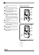
Removable internal parts
01 base plate
02 fire basket right rear
03 fire basket left rear
04 fire basket right
05 fire basket left
06 fire basket
07 side inner plate right rear
08 side inner plate left rear
09 baffle plate inner plate
10 side inner plate right
11 side inner plate left
12 ash pan
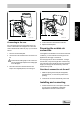
Preparing the connection to
the flue
When connecting the appliance to the flue, you can
choose to connect to the top or to the rear of the appli-
ance
An optional heat shield is available. By using this heat
shield you can reduce the distance to the combustible
material. See appendix "Distance from combustible
material". For a rear connection the escape plate
needs to be removed. You can do this with the assist-
ance of a screwdriver (1); see following figure.
09-20021-014
1
Fitting the heat shield
To fit the optional heat shield, proceed as follows:
1. Screw 2 M6 studs (1) with spacer (2) to the rear
wall.
2. Place the heat shield (3) and screw into place with
2 M6 flanged cap screws (4), see following figure.
1
2
09-20021-023
3
4
Connecting to the top
As standard, the appliance is delivered with the con-
nection collar fitted for a connection at the top, see fol-
lowing figure.
10
Subject to change because of technical improvements