“There Is No Substitute for Experience” DOW-KEY MICROWAVE 1U MS, MP, CB Matrix Series MS-1U18S-4/6-ENET CAN BUS RF SWITCH MATRIX Operator’s Manual Rev 1 THE RF/MICROWAVE SWITCHING TECHNOLOGY SOLUTION COMPANY
Copyright © Dow-Key Microwave Corporation 2012, all rights reserved. Information in this publication supersedes that in all previously published material. Specifications and price change privileges reserved. Printed in the U.S.A. Dow-Key is a registered trademark of Dow-Key Microwave Corp. Document Number: 49101-237 Revision 1 4822 McGrath Street, Ventura, CA 93003 Tel: (805) 650-0260 Fax: (805) 650-1734 Visit at www.dowkey.
WARRANTY Dow-Key Microwave Corporation warrants this product to be free from defects in material and workmanship for a period of 1 year from date of shipment. This warranty does not apply to defects resulting from product tampering or modification without DowKey’s express written consent. This warranty also does not apply to software, nonrechargeable batteries, power supplies, or problems arising from normal wear or failure to follow instructions.
Manual Revision History The revision history shown below lists all revisions and addendums created for this manual. The revision level increases numerically as the manual undergoes subsequent updates. Addendums are released between revisions and contain important change information that the user should incorporate immediately into the manual. When a new revision is created, all addendum associated with the previous revision of the manual are incorporated into the new revision of the manual.
Table of Contents 1 General Information...................................................................................................... 1 1.1 Introduction ........................................................................................................ 1 1.2 MS Matrices ....................................................................................................... 2 1.3 MP Matrices .......................................................................................................
.4.3 *RST .......................................................................................................... 34 6.5 System Commands .......................................................................................... 34 6.5.1 SYST:ERR?............................................................................................... 34 6.5.2 SYST:IPADDRESS? ................................................................................. 38 6.5.3 SYST:IPADDRESS xxx.yyy.zzz.aaa ...................
1 General Information 1.1 Introduction The Dow-Key Microwave 1U MS, MP, CB Switch Matrix series are electromechanical RF matrices. They come equipped with an Ethernet port which allows the user to easily access the matrix from anywhere in the world via TCP/IP on 100BaseT networks. Other interfaces included are an RS-232 port, an USB (used as virtual serial port) and a CAN Bus port. The 1U models are 1 Rack Unit high (1.
General Information 1.2 MS Matrices MS-Series stands for Multiple Switches. It is a matrix where a number of independent switches are populated on the rear panel or inside the matrix enclosure. From an RF point of view the switches are not interconnected and all switch’s RF ports are available to the user on the rear panel of the matrix. Depending on the size of the switch and the quantities needed, the matrix size can grow from 1RU to 4RU (or even larger).
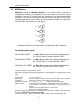
General Information 1.3 MP Matrices MP-Series stands for Multiplexer. It is a matrix with one input connecting to many outputs (only one at the time) or, since the RF switches are bi-directional, many inputs connected to one output (only one at the time). The switches are populated either on the rear panel or inside the matrix chassis. From an RF point of view the switches are interconnected and all input/output RF ports are available to the user on the rear panel of the matrix.
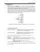
General Information 1.4 CB Matrices CB-Series stands for Crossbar. It is a matrix with several inputs connecting to several outputs. Only one input can be connected to one output at any given time. The switches are populated inside the matrix chassis and are interconnected so that any input can connect to any output and vice versa. All input/output RF ports are available to the user on the rear panel of the matrix.
General Information 1.
1.6 Safety Precaution Safety precautions should be observed before using this product and any associated instrumentation. This product is intended for use by qualified personnel who recognize the safety precautions required to avoid possible injury. 1.7 Inspection The Matrices were carefully inspected, both electrically and mechanically before shipment. After unpacking all items from the shipping carton, check for any obvious signs of physical damage that may have occurred during transit.
2 System Layout 2.
System Layout 2.2 Rear Panel Layout Figure 2-2 shows an example of a 1U model rear panel general layout. All models have common parts which include: • Power Entry Module with built in Fuse • Chassis Ground Post • 9-Pin D-Sub Female RS232 Connector • 4-Pin XLR Female CAN Bus / 12V power (output) Connector • RJ-45 Ethernet Connector • USB type A Connector Other parts that are not common to all models are Coaxial RF switches and/or RF connectors.
System Layout System Layout 2.3 Top View Layout Figure 2-3 shows the top view layout of all models.
System Layout 2.4 RF configuration Refer to appendix B.
3 Connections 3.1 3.1.1 Power Connection Line Voltage The matrix operates from a line voltage in the range of 110V to 240V at a frequency of 50 or 60Hz. Line voltage selection is automatic. CAUTION: Operating the unit on an incorrect line voltage may cause damage, possibly voiding the warranty. 3.1.2 Line Power Connection Perform the following steps to connect the matrix to line power: 1. Connect the female end of the supplied power cord to a grounded AC receptacle on the rear panel. 2.
Connections Insert small bladed screwdriver to release the fuse. Figure 3-1, Power Entry Module Line Voltage Fuse Rating Manufacturer Manufacturer Part No. 110-240V 1A, slow blow, 250Vac, ¼” x 1-1/4” Bel Fuse Inc. 3SB 1-R Table 3-1, AC Line Fuse Information 3.2 Ground Connection The rear panel GND ground screw (refer figure 2-2) should be connected to safety earth ground using #18 AWG or larger wire. 3.
Connections Pin 1 Pin 2 Pin 3 Pin 4 Pin 5 Pin 6 Pin 7 Pin 8 Pin 9 NC Transmit Receive NC Ground NC NC NC NC Table 3-2, RS232 Female Connector Pin Functions 3.4 CAN Bus Connection This connection allows the matrix controller to be easily interfaced to another Dow-Key Microwave Switch Extension Matrix, using a one-to-one (straight through) cable. However, the Matrix being interfaced must not have any internal, intelligent controller; it must be a simple RF Switch Extension Matrix.
Connections 3.5 Ethernet Connection The matrix comes equipped with an Ethernet port (RJ45 connector) which allows the user to easily access the matrix from anywhere in the world via TCP/IP on 100BaseT networks. See Section 4 and Section 6 for descriptions regarding how to connect to, configure, and operate the matrix over this 100BaseT Ethernet connection. 3.6 USB Port Connecting the matrix to a PC’s USB port should result in a “Found New Hardware” event.
4 Configuring the Matrix for Operation 4.1 Matrix Configuration The ‘brain’ inside Dow-Key Matrices, referred to as the “Matrix Controller”, has been designed to be as general as possible in regards to how many switches of what positions it may control.
Configuring the Matrix 4.3 Adding and Deleting Switches The following rules apply when adding a switch to the Matrix Configuration (the desired ID to add is referred to as the “target ID”): ‐ The desired switch to ADD must be connected to the matrix before executing the ADD procedure.
Configuring the Matrix Example procedure: Adding a switch to the Configuration usually starts by finding the ID of the physical switch to add. Select Main Menu>System Settings>Find Switch ID and follow the instructions in Section 5.2.3 Find Switch ID. TAKE NOTE OF THE INFORMATION REGARDING SWITCH FIRMWARE REVISION IN STEP 5. If the switch’s ID is the one desired to add (0 or N), the switch may be left connected and the BACK key may be pressed to return to the Main Menu.
Configuring the Matrix 4.5 Connection to an Ethernet The use of a standard “Straight Through” Ethernet cable is required to connect the matrices to an Ethernet LAN hub. Connection to a single computer requires the use of “Crossover” Ethernet cable.
Configuring the Matrix 4.5 Testing Ethernet Communication The matrix’s ability to communicate should be tested once it has been configured and connected to an Ethernet network. Connection thru a network: Assuming the matrix’s default IP address setting has not been changed from obtaining the IP address dynamically, take note of its IP address during the boot-up process (or se section 5.2.4 to read its IP address).
Configuring the Matrix In both the above scenarios a valid and working connection will yield a response similar that shown in the example below: C:\>ping 200.169.200.181 Pinging 200.169.200.181with 32 bytes of data: Reply from 200.169.200.181: bytes=32 time=5ms TTL=64 Reply from 200.169.200.181: bytes=32 time=2ms TTL=64 Reply from 200.169.200.181: bytes=32 time=2ms TTL=64 Reply from 200.169.200.181: bytes=32 time=3ms TTL=64 Ping statistics for 200.169.200.
5 Manual (LOCAL) Operation 5.1 The Keypad / LCD Interface Power On: Position the rocker switch on the rear panel of the Matrix to the on position (Figure 2-2) to turn on the matrix. ! Note: The booting sequence will last about 15 seconds in which the LCD will appear blank. The figure above shows the LCD/Keypad (sometimes referred to as the “User Interface”, or “UI”) at the top level of UI screens. The “COMM” LED should normally be blinking green as an indication of normal program execution.
Manual (LOCAL) Operation UP and DOWN serve as “scroll up”, “scroll down”, “increment”, or “decrement”. Many data fields’ values are modified by UP and DOWN, and many of those allow the pressing and holding of the UP and DOWN keys to cause an acceleration of the incrementing or decrementing. The keypad’s upper left diagonal key is referred to as UP DIAG. This key serves as “back”, “clear”, or “escape”. The keypad’s lower left diagonal key causes no action in the context of any screen.
Manual (LOCAL) Operation 5.2 Main Menu 5.2.1 Switching Operations Switch Operations Menu Set Switch Positions View the currently set position and change the position of a switch who’s ID has been configured to the matrix. Use the arrows to change switch and position numbers. Refer to Appendix B to set the RF switches in the correct desired positions. Current Positions View the currently set positions of all switches whose ID’s have been configured to the matrix.
Manual (LOCAL) Operation Recall Positions Recall from non-volatile memory the state of the positions of all switch ID’s configured to the matrix, saved as 1 through 30, and set the positions of those switches. Clear Positions Cause all switches configured to the matrix to assume their default position. For most switches this is position 0 (open positions). Note that all Dow-Key switches have “open” defined but not all switch types have an actual open position, such as a transfer switch.
Manual (LOCAL) Operation 5.2.2 Error Operations View the contents of the Error Log (see Section 6.5.1). Each entry is displayed with the oldest being first (First In First Out), showing the Error Record Number (its place in the Error Log), an associated Error Code, an associated Error Data, and a text explanation of the Error. The Error Data contains various parameters associated with certain Errors.
Manual (LOCAL) Operation 5.2.3 System Settings System Settings Menu ! Important Note: The matrix controller is designed to offer the maximum expandability and flexibility possible and therefore has features common to other Dow-Key matrix models. The here described ‘Add’, ‘Delete’ and ‘Find Switch ID’ features are some of those that, although available and fully functioning, should only be used if needed and appropriate. Switches may be added and deleted from the Matrix Configuration using these commands.
Manual (LOCAL) Operation 4. NOTE: this operation “puts the matrix’s switches to sleep” thereby rendering the matrix inoperable during the process. ENTER or CLEAR or rebooting returns the matrix to normal. 5. NOTE: proper performance of Find Switch ID relies on the behavior of Dow-Key Switch firmware revision 4 and above – revision 3 and below does not allow “putting the switch to sleep”.
Manual (LOCAL) Operation 5.2.4 Ethernet Options Actual changes to the Ethernet variables referred to below will not take effect nor be shown on the front panel until the matrix has been powered down and back up. See Sections 4 and 6 for more information regarding use of Ethernet to control the matrix. Ethernet Menu Set/Acquire IP Address View and/or modify the current IP Address and Acquisition Mode, Static or Dynamic (DHCP off or on). Set Subnet Mask View and/or modify the current Subnet Mask.
Manual (LOCAL) Operation 5.2.5 LCD Options View and adjust the brightness and contrast of the LCD. Changes made here are persistent over power down and up. 5.2.6 Set RS232 Baud Rate View and select the Serial Port’s Baud rate from a set of preselected values from 1200 to 115,200 b/s (see Section 3.3). Use the arrows to change the baud rate settings. Default value is 9600b/s. 5.2.7 Set GPIB Address View and select the GPIB’s address. The default address is 9. Not applicable for ENET (Ethernet) models.
6 Remote Operation 6.1 Introduction to SCPI SCPI is a command structure that is based on the IEEE-488.2 specification which Dow-key has adapted to work with Ethernet, RS-232 and USB controls. The matrix has internal software loaded that uses SCPI command structure. SCPI is the abbreviation of Standard Commands for Programmable Instruments. These commands are standard messages for the (remote) control of programmable instruments, which are sent by the Ethernet and/or RS-232 and/or USB controller.
Remote Operation 6.3 Command Separators and conventions • • • • • A colon (:) is used to separate a command keyword from a lower level keyword. A blank space is used to separate a parameter from a command keyword. A comma (,) is used if a command requires more than one parameter. A semicolon (;) is used to combine multiple commands into one message string. Commands from the same subsystem are permitted to skip repeating the upper-level keyword. Eg.
Remote Operation 6.4 Common Commands The following contains the common commands of SCPI that the Ethernet controller is compatible with. The possible error codes assume that the correct syntax is used and, in case of a multiple command string the string is not too long. If these conditions are not met, any given command can generate these error codes: 3, 4, 30 6.4.
Remote Operation 6.4.2*OPC? Syntax *OPC? Description This query returns an ASCII character “1” when all pending operations have been finished. Result ASCII character “1”. Possible error codes None Example 1 *OPC? Result “1” Example 2 :SWIT1 4; SWIT2 4; *OPC? Result “0” Timing In example 2 the matrix did not have the time to execute the command. Hence a “0” is returned. A subsequent *OPC? will return a “1” as shown in example 1.
Remote Operation 6.4.3 *RST Syntax *RST Description This command performs a device reset. This will set the instrument so that all switches are in the default state. For SPnT switches the default state is: all RF ports are open. For a transfer switch the default state is: position 1 is closed. Possible error codes 11, 12, 13 Timing As a rule of thumb electromechanical switches require approximately 30ms to switch position.
Remote Operation Example “SYST:ERR?” Result was “1, INVALID CHARACTER”, check for more errors. Description: This error is no longer supported. The error code is maintained and reserved for legacy purposes only. “SYST:ERR?” Result was “2, OUTPUT BUFFER OVERFLOW”, check for more errors. Description: This error is no longer supported. The error code is maintained and reserved for legacy purposes only. “SYST:ERR?” Result was “3, TOO MANY COMMANDS”, check for more errors.
Remote Operation SYST:ERR?” Result was “10, SWITCH DID NOT RESPOND”, check for more errors. Description: One of the switches did not respond to a position query. E.g. CAN bus communication failure or damaged switch. SYST:ERR?” Result was “11, SWITCH’S RESPONSE INVALID”, check for more errors. Description: A switch responded but with the wrong response code. This error is related to wrong internal CAN bus communication codes. SYST:ERR?” Result was “12, SWITCH’S POSITION INCORRECT”, check for more errors.
Remote Operation SYST:ERR?” Result was “30, COMMAND UNRECOGNIZED”, check for more errors. Description: This error code is generated when the commanded string does not contain any valid keyword (e.g. Route, System, *IDN?, *RST, ….) at all. SYST:ERR?” Result was “36, ID IS OUT OF RANGE”, check for more errors. Description: A non existing switch ID has been commanded. Eg. Sending Route:Switch11 8. When switch 11 does not exist. SYST:ERR?” Result was “50, UNABLE TO AQUIRE IP ADDRESS”, check for more errors.
Remote Operation 6.5.2 SYST:IPADDRESS? Syntax SYSTem:IPADDRESS? Description Returns the matrix IP address. Result xxx.yyy.zzz.aaa Possible error codes None 6.5.3 SYST:IPADDRESS xxx.yyy.zzz.aaa Syntax SYSTem:IPADDRESS xxx.yyy.zzz.aaa Description Sets system IP address to xxx.yyy.zzz.aaa. Possible error codes 5 Factory default value 200.169.200.180 Power on behavior Keeps last value *RST effect None Timing In order for the new IP address to take effect the matrix needs to be power cycled.
Remote Operation 6.5.4 SYST:TCPPORT? Syntax SYSTem:TCPPORT? Description Returns the matrix TCP Port number. Result n Possible error codes None 6.5.5 SYST:TCPPORT x Syntax SYSTem:TCPPORT x Description Sets the matrix TCP Port number to x. Possible error codes 5 Factory default value 10 Power on behavior Keeps last value *RST effect None Timing In order for the new TCP Port to take effect the matrix needs to be power cycled.
Remote Operation 6.5.6 SYST:GATEWAY? Syntax SYSTem:GATEWAY? Description Returns the matrix gateway address. Result xxx.yyy.zzz.
Remote Operation 6.5.7 SYST:GATEWAY xxx.yyy.zzz.aaa Syntax SYSTem:GATEWAY xxx.yyy.zzz.aaa Description Sets matrix gateway address to xxx.yyy.zzz.aaa. Possible error codes 5 Factory default value 200.169.0.0 Power on behavior Keeps last value *RST effect None Timing In order for the new Gateway address to take effect the matrix needs to be power cycled. 6.5.8 SYST:MASK? Syntax SYSTem:MASK? Description Returns the matrix subnet mask address. Result xxx.yyy.zzz.
Remote Operation 6.5.9 SYST:MASK xxx.yyy.zzz.aaa Syntax SYSTem:MASK xxx.yyy.zzz.aaa Description Sets the matrix subnet mask address to xxx.yyy.zzz.aaa. Possible error codes 5 Factory default value 255.255.255.0 Power on behavior Keeps last value *RST effect None Timing In order for the new Mask address to take effect the matrix needs to be power cycled. 6.5.10 SYST:MACADDRESS? Syntax SYSTem:MACADDRESS? Description Returns the matrix mac address.in hex format Result aa.bb.cc.dd.ee.
Remote Operation 6.5.11 SYST:SERIALNUMBER? Syntax SYSTem:SERIALNUMBER? Description Returns the matrix serial number. Result n Possible error codes None 6.5.12 SYST:TIMEOUT? Syntax SYSTem:TIMEOUT? Description The Timeout is used to automatically close the TCP/IP socket after a certain amount of seconds of inactivity on the port. Returns the Time out setting for the TCP/IP connection (n is in seconds). n = 0 means no Time out is set.
Remote Operation 6.5.13 SYST:TIMEOUT x Syntax SYSTem:TIMEOUT x Description The Timeout is used to automatically close the TCP/IP socket after a certain amount of seconds of inactivity on the port. Sets the Time out setting for the TCP/IP connection (n is in seconds). x = 0 means no Time out is set.
Remote Operation 6.5.14 SYST:STATUS? Syntax SYSTem:STATUS? Description This command will return all Switch positions, Local/Remote mode, Power supply status, High temperature alarm status, Fan stall alarm and Errors list separated by a semicolon. Note 1: Power supply status, High temperature alarm status and Fan stall alarm are only returned if enabled.
Remote Operation 6.5.15 SYST:SCREENSAVER? Syntax SYSTem:SCREENSAVER? Description This command will return the screen saver time settings n (n is in minutes). Possible values for n are 0, 2, 3, 4, 5, …… Note that 1 is not a valid value. 0 = Screen saver is disabled Possible error codes 5 Factory default value 5 Power on behavior Keeps last value *RST effect None 6.5.16 SYST:SCREENSAVER x Syntax SYSTem:SCREENSAVER x Description This command will set the screen saver time settings x (x is in minutes).
Remote Operation 6.6 Switch [Module] Command Set The following contains the switch [module] commands of SCPI that the Ethernet control is compatible with. 6.6.1 :SWITch[:VALue] Syntax [ROUTe]:SWITch[:VALue] Description This command is used to control the position of the switches. The switch specified by the numeric suffix is set to position .
Remote Operation 6.6.2 Setting switch x to position n x = switch [module] address. n = position to set and must be within the switches parameter. (Example: SP10T valid positions are 0 thru 10 only). Examples: • ROUTE:SWITCHx n • ROUT:SWITCHx n • ROUTE:SWITx n • ROUT:SWITx n • :SWITCHx n • :SWITx n • ROUTE:SWITCHx:VALUE n • ROUTE:SWITCHx:VAL n • :SWITx:VAL n Possible error codes 5, 10, 12, 13 Factory default value N.a.
Remote Operation 6.6.3 Requesting Switch x current position x = switch address. Examples: • ROUTE:SWITCHx? • ROUT:SWITx? • :SWITx? Result: Returns the current position of switch x. Possible error codes 10, 11, 12, 13 Timing The timing to execute a command depends on the length of the command (in case of concatenated commands). As a rule of thumb electromechanical switches require approximately 30ms to switch position.
Remote Operation 6.7 DHCP Command Set The following contains the DHCP (Dynamic Host Configuration Protocol) commands of SCPI that the Ethernet control is compatible with. 6.7.1 SET:DHCP ON or SET:DHCP OFF Syntax SET:DHCP ON I OFF Description Turns DHCP mode ON or OFF Possible error codes 5 Factory default value OFF Power on behavior Keeps last value *RST effect None Timing In order for the new DHCP settings to take effect the matrix needs to be power cycled. 6.7.
Remote Operation This page intentionally left blank 51
RS232, USB and Ethernet Command description for standard matrices Command Syntax Response 1 *IDN? MS-1U18S-4/6-ENET 2 *OPC? 1 or 0 3 *RST 4 5 6 7 8 9 10 11 12 13 14 15 16 17 18 19 ROUTE:SWITCHx y or :SWITCHx y ROUTE:SWITCHx? or :SWITCHx? SET:DHCP ON or SET:DHCP OFF GET:DHCP SYST:IPADDRESS? SYST:IPADDRESS xx.yy.zz.aa SYST:TCPPORT? SYST:TCPPORT x SYST:GATEWAY? SYST:GATEWAY xx.yy.zz.aa SYST:MASK? SYST:MASK xx.yy.zz.
Remote Operation Note: 1. Commands are NOT case sensitive. 2. Every command and response on the Ethernet and serial port should have “\r\n” Carriage return (0x0D) and Line Feed (0x0A) at the end. 3. Multiple commands with same header can be given in a single command line. e.g. SYST:IPADDRESS?;TCPPORT?;SERIALNUMBER 2 or ROUTE:SWITCH1 2;SWITCH1?; note that the commands have to separated by ‘;’ 4. The default settings for the Ethernet interface are: a. IP Address: n.a. b. IP Port number: 10 c.
7 Web Page Server (HTTP) 7.1 Web Page Server Control The matrix may be controlled by way of web pages served by the matrix over its Ethernet port. With the matrix properly connected to an Ethernet (see Section 4), type the matrix’s current IP address into a browser’s Address Bar. The following page should appear: The Operator may select ‘Matrix Control’, ‘Matrix Configuration’, or ‘Matrix Status’; ‘Factory Configuration’ is reserved for the sole use by Dow-Key Microwave.
Web Page Server 7.2 Matrix Control Clicking on ‘Matrix control’ will show the below page. Remote mode commands may be typed into the Command text box and then clicking on the ‘Send’ button. See section 6 for the remote command list and its syntax. If the command implies that the matrix responds (for instance when querying the matrix) the matrix’s response will be shown next to the ‘Answer:’ label. The bottom half displays the current position of all switches currently configured to the matrix.
Web Page Server 7.3 Matrix Configuration Clicking on ‘Matrix configuration’ will show the below page. ! Important Note: The matrix controller is designed to offer the maximum expandability and flexibility possible and therefore has features common to other Dow-Key matrix models. The here described ‘Add a Switch’ and ‘Remove a Switch’ features are some of those that, although available and fully functioning, should only be used if needed and appropriate.
Web Page Server 7.4 Matrix Status Clicking on ‘Matrix status’ will show the below page. This page displays the current status of alarm sources (power supplies, fans, temperatures). If the matrix does not have a redundant power supply, fans with stall sensors and temperature sensors, than this page will not display any of this information.
Appendix A Technical Specifications Model: MS-1U18S-4/6-ENET Configuration: Four SP6T switches mounted on the rear panel RF Connectors: SMA (on rear panel) Frequency range: DC to 18 GHz Return loss (VSWR) Insertion loss Isolation RF Power: Frequency (GHz): VSWR (Ratio max): Insertion Loss (dB max): Isolation (dB min): RF Power (Watts CW max): DC ‐ 3 1.20 : 1 0.2 80 125 3‐8 1.30 : 1 0.3 70 90 8 ‐ 12.4 1.40 : 1 0.
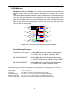
Appendix B RF Configuration Model: MS-1U18S-4/6-ENET Four normally open SP6T switches (Dow-Key part number: 565-5208-3-ROHS) mounted on the rear panel. The switches are not interconnected RF wise as shown below. Note that all switches are bi-directional. Hence each RF port can be considered an input or an output.