
Installation Guide
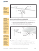

F. Pivot the Strongback and the
Support Bar to align the mounting
holes of the Support Bar with the
Pivot Tab on the Mounting Sleeve.
Insert the 3/8” x 1-1/4” bolt and
one flat washer thru the Support
Bar and Mounting Tab and secure
it with the remaining flat washer,
lock washer and hex nut.
(See
Figure 2-3)
G.
Torque
hardware on both ends of
Support Bar at 32-34 ft.-lbs.
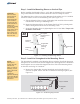
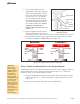
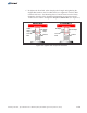
Return and tighten the Pivot Bolt.
The Pivot Bolt cannot be left loose -
the Mounting Sleeve Vertical Towers must be firmly clamped to the sides of
the Strongback eliminating any gaps between the Vertical Towers and the
Strongback. (See Figure 2-4)Torque to 75-85 ft.-lbs.
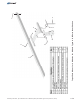
Figure 2-3: Securing Support Bar to
Mounting Sleeve
5 of 8
CAUTION:
This is a two
person activity.
Module Rails are
unstable before
they are fully
secured to the
Support Angles.
Module Rails must
be held in place
by one person
while the second
person aligns and
secures them to
the Support
Angles. Failure to
do so could lead
to serious
personal injury.
Lock
Washer
3/8” Boltx 1-1/4”
Pivot
Tab
Flat Washers
Support Bar
3/8” Hex Nut
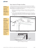
Step 3: Attach the Module Rails to the Support Angles
Module Rails run in an E-W direction and are secured to the two Support Angles of
the Strongback (these are welded to the Strongback) using 3/8” x 1” bolts and
hardware. There are two Module Rails to install.
A. Align the Module Rail mounting holes with the holes of the Support Angle
and secure with 3/8” x 1” bolts and hardware. Finger-tighten for now. (See
Figure 3-1)
B. Continue in this manner and install the next Module Rail.
Figure 2-4: Tighten and Torque the Pivot Bolt
Strongback
Towers
No Gaps
No Gaps
Pivot
Bolt
Strongback
Towers
Visible
Gaps
Visible
Gaps
Pivot
Bolt
WRONG
CORRECT
Assembly Instructions, Top-of-Pole Mount for 4 Modules (TPM4) For Module Types A & B (Version 2, Rev D)