
Operation Manual

10
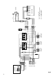
Fig. 26
control board
Segment 1 Segment 2 Segment 3
1C
main fan
main connection
coin box
coin box
(use only coin box
with fan delay)
C1 = capacitor 5µF
SD = inductor for earth conductor
1K=
contactor for fans
2K=
contactor for lamps
rechts/rightTür/door links/left
remove jumper
fan
L
time
N
4
NPE
123
L1 L2 N PE
4213
PEL3 N
1234
L1
N
time
1324
LN
L
1234
PE
N
startup
SD
PE
N
L3
L2
L1
LN
time
time
fan
NC
L
L
N
N
PE
TH
gn-ye
br
bl
grey
bl
24 146A2264
31135A1531
14 A2
13 A1
K 2K1
2Kl
1Kl
1Bu 2Bu Bu3
3
Kl
Kl
4