
Operation Manual

5
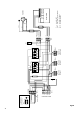
System assembly is described step by step in the following
sections. Please ensure that electrical wiring and
connection is performed by a certified electrician in
keeping with VDU and local EVU regulations.
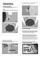
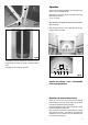
À Baseplate
Begin the assembly by removing the baseplate (D)
from package 4, and placing it at the intended location
of the system.
Note:
The baseplate must be placed flat and level! For
orientation purposes, the rear positioning tongue is
provided with an adhesive label.
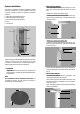
E
A
B
C
Fig. 1
D
Fig. 2
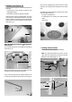
Á Right tanning element
Remove the right element (A) from package 1. You must
now carry out the initial assembly of the two stand
feet.
Stand foot, facing side lower right:
From the accessory pack, take the stand foot (4), two
M10 nuts (5) and washers (6), and assemble the foot
as shown in Fig. 3.
Fig. 3
4
5/6
Stand foot, facing side lower left:
From the accessory pack, take the stand foot (7), two
M10 nuts (5) and washers (6), and assemble the foot
as shown in Fig. 4
Fig. 4
7
6
5
Ensure that the installation plate of the stand foot is
correctly positioned for connection to the next element
(Fig. 4).
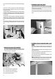
 Left tanning element
Remove the left element (B) from package 2, and
assemble the stand foot (8) as follows:
From accessory pack 2, take 2 distance collars (9), two
M10 nuts (10) and 2 lock-washers (11), and assemble
as shown in Fig. 5.
Note: The bearing (12) for the door element is already
fitted in stand foot (8).
9
12
10/11
8
Fig. 5
1
14
13
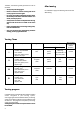
System Installation
The system is delivered in several separately packed
sections for transport to its final installation point. The
complete package contains the following individual
elements:
A right tanning element (package 3)
B. left tanning element (package 2)
C. door tanning element (package 1)
D. base
E. exhaust unit