
Operation Manual

8
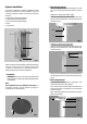
Now screw the castor (26) onto the retaining bolt (25) (Fig.
16).
Lift the door element with the pre-assembled bearing
bolt (27) onto the installation plate (12), and slide the
bearing into place.
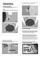
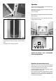
To assemble the upper bearing (Fig. 18), you will need the
installation plate (28), which is first loosely assembled
using the two threaded bolts (29), the nuts (30) and lock-
washers (31).
Swing the door element over the installation plate (28) so
that the upper bearing point of the door element (32) is
positioned opposite the opening in the installation plate
(28).
Now let the installation plate (28) drop down over the
upper bearing, and tighten the two nuts (30) firmly (Fig.
18).
29
28
30
31
Fig. 18
32
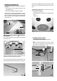
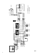
Æ Electrical connection of the elements
All 3 elements have their electrical connections at the
top, and are connected to the control unit (33) by means
of the 3 plugs (34 - 36) (Fig. 19).
Fig. 19
3334
35
36
Ç Installing the upper trim panels
Finally, fit the three trim panels (37) around the upper
edge of the system (Fig. 20), using for each panel two
self-tapping screws (38) on the outside, and two M4
screws in the central area.
Ensure that a distance sleeve is placed between the
trim panel and rear wall of the unit at each attachment
point.
32
28
37
38
Fig. 20
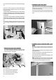
È Installation of main connection cable / cover
panel
The main connection cable (39) is pre-assembled to
the control unit (33), and lies rolled up on the exhaust
unit.
Take the cable (39) and lead it down along the side of
the system (Fig. 21).
Then fit the cable tension-relief device (40) (from the
accessory pack) to the cable (Fig. 22).
Now remove the cover panel (41) from package 3, and
fit it as shown in Fig. 23.
Note: The existing screws in the rear walls are used
for the attachment of the cover panel (41). These screws
must be removed before fitting the cover panel.
Fig. 21
33 = Control unit
34 = Connection cable, right element
35 = Connection cable, left element
36 = Connection cable, door element
39 = Main connection cable
39
39